background image

3

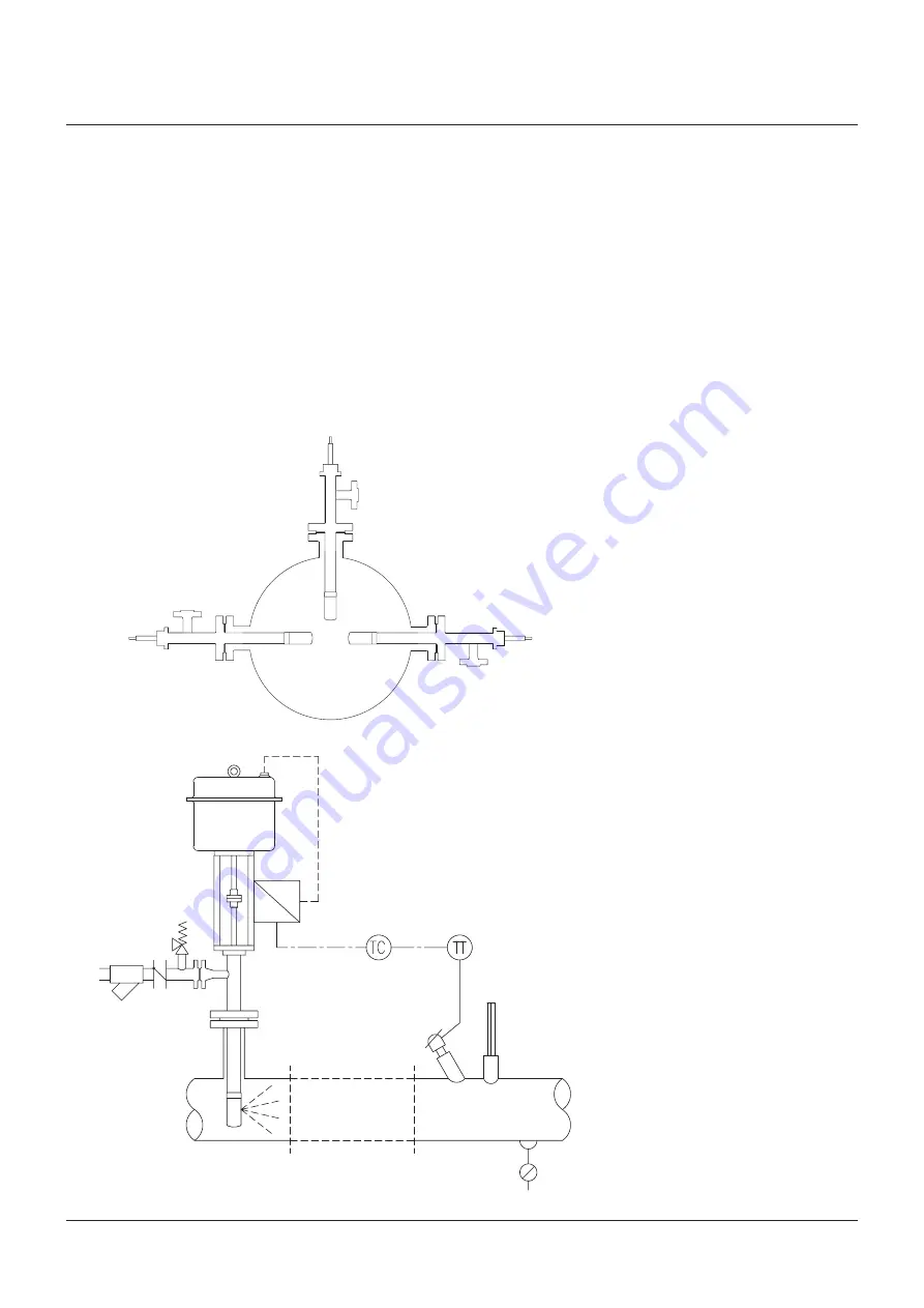
Figure 6

safety valve

Check valve

strainer

YarwaY 

A.T.-Temp CryogeniC desuperheATer sTAndArd duTy

InstallatIon and MaIntenance InstructIons

The liquid supply should be of a good quality; 
clean and filtered, and should have a constant 
pressure as specified in the order documents. 
each liquid supply line should be protected with 
its own individual strainer with a maximum 
element perforation size of 0.1 mm (0.4 mm 
acceptable for nozzles ‘e’ size and up).
Where there are positive shut-off components 
in the liquid supply (including electric actuators) 
then a safety relief valve of an approved type 
should be fitted. As in the case of the process 
pipework, use gasketing and bolting in 
accordance with the relevant piping code. Flush 
out the liquid line before connecting to the 
A.T.-Temp Cryogenic desuperheater mounting 
flange (see Figure 6).

Figure 5

yarway supplies the A.T.-Temp Cryogenic 
desuperheater as follows:
identification number:
xx. 37. xxxxx -  Fabricated type with 

non-balanced stem.

xx. 47. xxxxx -  Fabricated type with 

semi-balanced stem and 
oversized trim all with the spray 
cylinder tack welded to the body 
extension pipe.

note:

 horizontal orientated A.T.-Temp 

Cryogenic desuperheater has to be installed 
with a support for weight compensation.

pipe bends should always be of the long radius 
type to assist in keeping the liquid droplets in 
suspension, until complete evaporation has 
taken place. installation may be in vertical or 
horizontal piping, but the direction of liquid 
injection should always be with the process 
gas flow.
The A.T.-Temp Cryogenic desuperheater may 
be mounted at 90° to the process pipe, for 
all flow orientations, but avoid installation in 
the vertically downwards position, wherever 
possible (see Figure 5).

Summary of Contents for Yarway

Page 1: ...body or use the hoisting lug if provided Do not use the water inlet connection yoke actuator or any of its accessories for lifting Leave the flange covers in place during transportation until ready to install in the pipework When installing the A T Temp Cryogenic desuperheater use gaskets and bolting material in accordance with the relevant piping code for example ASME ANSI B31 3 or EN Place the g...

Page 2: ... Pneumatic or E P positioner Figure 1 Check for damages Check for damages Figure 2 Figure 3 Liquid flange positions Process line Process gas flow Handwheel positions Process line Process gas flow The minimum pipe run required downstream of the A T Temp Cryogenic desuperheater varies with each individual application and would be specified by Yarway at the enquiry stage This straight run is needed t...

Page 3: ...cting to the A T Temp Cryogenic desuperheater mounting flange see Figure 6 Figure 5 Yarway supplies the A T Temp Cryogenic desuperheater as follows Identification number xx 37 xxxxx Fabricated type with non balanced stem xx 47 xxxxx Fabricated type with semi balanced stem and oversized trim all with the spray cylinder tack welded to the body extension pipe Note horizontal orientated A T Temp Cryog...

Page 4: ...rdination between instrument signals and temperature are attained adjustment of the set point can be made and the system transferred to automatic operation It is recommended to record the various process coordinates over a sustained period to verify operation adjusting where necessary Maintenance Note maintenance of the A T Temp Cryogenic desuperheater is straight forward and does not require any ...

Page 5: ...ng wire brush and or honing device Cleanless of the packing area is vital for proper valve sealing Do not use grease or lubricants in combination with PTFE Chevron type packing The actual packing design is mentioned on the project related valve drawing Only ever use genuine Yarway components as they are supplied as matched sets see Figure 9 Disassembly see Figure 8 The A T Temp Cryogenic desuperhe...

Page 6: ... material removed Insert the A T Temp Cryogenic desuperheater into the pipework and check that the nozzle is orientated correctly with the spray with the direction of the gas flow Apply a suitable lubricating compound to the bolts and nuts and tighten evenly in accordance with the manufacturer s recommendations Before connecting the liquid line flush through and check for any contamination or rest...

Page 7: ...plate SA 182 F304L 19 Name plate AISI 316 20 Lock nut Stainless steel 21 Coupling SA 182 F304L 23 Securing washer Stainless steel 24 Vapor flange SA 182 F304 F304L dual certified 25 Guiding PTFE 26 Spring AISI 631 17 7 PH 27 Shoulder bolt SA 320 B8 CL 2 28 Securing washer Stainless steel 29 Flange female SA 182 F304L 30 Flange male SA 182 F304L 31 Extension pipe SA 312 TP304L 32 Piston rings Alumi...

Page 8: ...rred Before placing the A T Temp Cryogenic desuperheater into service stroke valve spindle a few times and inspect other components such as actuator seals etc to ensure correct functioning Follow the procedure for installation as detailed in the operating and maintenance instruction manual Note materials and data of units supplied may deviated from this Instruction Manual Please consult order docu...

Reviews: