4310 Wireless Position Monitor
Instruction Manual
October 2009
8
W9637
ROTARY
MOUNTING
BRACKET
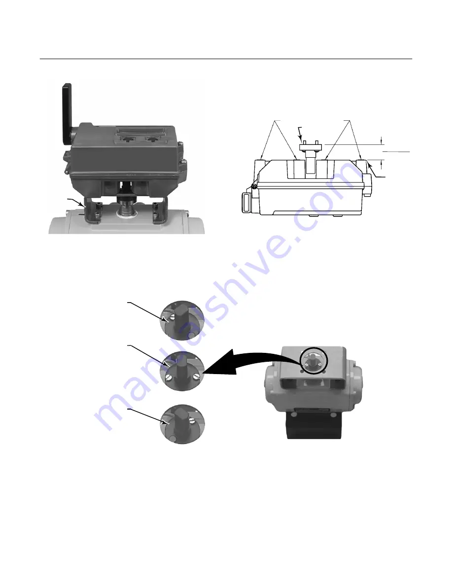
Figure 7. For Rotary
−
Shaft Actuators (Typical Mounting
Bracket)
GE42123 Rev A
MOUNTING INSERT FACES
mm
(INCH)
MAGNET
ASSEMBLY
BASE
OF HOUSING
MOUNTING
INSERT
FACES
0.77
$
0.03
19.5
$
0.8
Figure 8. Mounting—Rotary Magnet Array
ORIENTATION
AT ONE TRAVEL
EXTREME
ORIENTATION
AT MID
−
TRAVEL
(FLATS PARALLEL
TO 4310 HOUSING
CHANNEL)
ORIENTATION
AT THE OTHER
TRAVEL EXTREME
W8836
−
1A
W8836
−
1B
Figure 9. Feedback Assembly Orientation
3. Attach the wireless position monitor to the
mounting bracket using the 4 mounting bolts, as
shown in figure 7.
4. Check for clearance between the magnet
assembly and the positioner feedback slot.
5. Once the instrument is mounted perform the local
interface calibration procedure, as described on
page 12. Verify the feedback array is centered
throughout the entire rotating range.


