


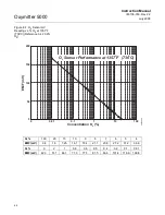


Oxymitter 5000
6-10
Instruction Manual
IM-106-350, Rev 2.2
July 2008
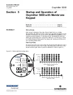
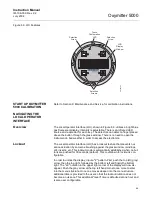
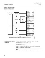
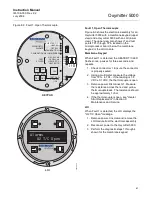
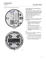
OXYMITTER 5000 TEST
POINTS
Refer to Figure 6-6. System test points are located on the board below the
LOI module. Test points 1 through 6 allow you to monitor with a multimeter:
the heater thermocouple, the O
2
cell millivolt, and the process O
2
.
• TP1 and TP2 monitor the oxygen cell millivolt output which equates to
the percentage of oxygen present.
• TP3 and TP4 monitor the heater thermocouple.
• TP5 and TP6 monitor the process gas or the calibration gas parameter.
Figure 6-6. Oxymitter 5000 -
Test Points
38730090
TP1
J1
TP2
TP3
RED
YEL
GRN
ORG
TP4
TP5
TP6
Summary of Contents for Oxymitter 5000
Page 2: ......
Page 6: ......
Page 12: ......
Page 22: ...Oxymitter 5000 xii Instruction Manual IM 106 350 Rev 2 2 July 2008 ...
Page 42: ...Oxymitter 5000 1 20 Instruction Manual IM 106 350 Rev 2 2 July 2008 ...
Page 62: ...Oxymitter 5000 2 20 Instruction Manual IM 106 350 Rev 2 2 July 2008 ...
Page 74: ...Oxymitter 5000 4 6 Instruction Manual IM 106 350 Rev 2 2 July 2008 ...
Page 78: ...Oxymitter 5000 5 4 Instruction Manual IM 106 350 Rev 2 2 July 2008 ...
Page 94: ...Oxymitter 5000 7 6 Instruction Manual IM 106 350 Rev 2 2 July 2008 ...
Page 140: ...Oxymitter 5000 9 22 Instruction Manual IM 106 350 Rev 2 2 July 2008 ...
Page 184: ...Oxymitter 5000 B 2 Instruction Manual IM 106 350 Rev 2 2 July 2008 ...
Page 204: ...Oxymitter 5000 D 14 Instruction Manual IM 106 350 Rev 2 2 July 2008 ...
Page 222: ...Oxymitter 5000 E 18 Instruction Manual IM 106 350 Rev 2 2 July 2008 ...
Page 224: ...Instruction Manual IM 106 350 Rev 2 2 July 2008 Index 2 Oxymitter 5000 ...


