SAG582127000
System Application Guide
Issue AF, February 26, 2014
Spec. No. 582127000 (Model 721
NPBB
)
Page 28 of 125
This document is property of Emerson Network Power, Energy Systems, North America, Inc. and contains confidential and proprietary information owned by Emerson Network Power, Energy
Systems, North America, Inc. Any copying, use, or disclosure of it without the written permission of Emerson Network Power, Energy Systems, North America, Inc. is strictly prohibited.
List 93: Optional Battery Tray, Pre-Cabled
Features
♦
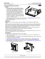
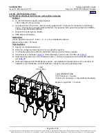
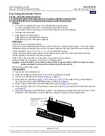
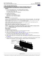
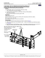
Each List 93 provides one (1) battery tray factory
mounted in the 23” wide system relay rack specified
when ordered. Each battery tray holds four (4) 12V
front terminal valve regulated lead acid (VRLA)
batteries. Battery cabling is factory provided and
connected to the system’s main busbars. Batteries
are configured as one (1) 48V string per tray.
♦
Battery trays can be ordered with or without a battery
disconnect circuit breaker. When a circuit breaker is
ordered, it is provided in the -48V lead of each battery
string (1 circuit breaker per tray).
♦
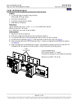
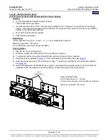
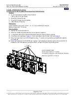
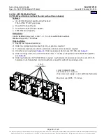
Battery tray dimensions are 21.3” wide X 24.4” deep. Refer to “
” under
PHYSICAL
SIZE INFORMATION
for a typical battery tray arrangement.
♦
Battery spacers included.
Restrictions
Designed to accommodate the batteries listed under “
in the ACCESSORY DESCRIPTIONS
section.
A single battery tray must mount at bottom of relay rack. Multiple battery trays must mount starting at bottom
of relay rack and working upward. Factory spaces battery trays 6RU, 7RU, or 8RU apart as determined by
battery selected. If no battery selected, factory spaces battery trays 8RU apart. Spacing can be increased
above that required for the battery selected up to a maximum of 8RU.
Cable size for each tray is 2AWG for optional battery disconnect circuit breaker selected up to 100A and
1/0AWG for circuit breaker selected over 100A or if circuit breaker is not selected.
Maximum number of List 93 per relay rack is four (4).
Not a stand-alone battery system. Must be used as part of a power system that includes a List 1 (List 2, List
3, List 5, or List 6) with a List 21, 22, 23, or 24 and a List 30.
Ordering Notes
1) Order up to four (4) battery trays per relay rack, as required.
2) Order battery cable termination kit, one per bay. P/N 553584 for use with List 21, P/N 555478 for use
with Lists 22, 23 and 24.
3) Order batteries separately. See “
in the ACCESSORY DESCRIPTIONS section. Battery cables
and lugs factory provided and connected.
4) If optional battery tray battery disconnect circuit breaker is desired, order per “
Battery Disconnect Circuit Breaker and Housing Kits
in the ACCESSORY DESCRIPTIONS section.
5) If optional battery tray front battery cover is desired, order per “
Optional Battery Tray Front Battery Cover
in the ACCESSORY DESCRIPTIONS section.
P/N 553584
P/N 555478

