


SAG582127000
System Application Guide
Issue AF, February 26, 2014
Spec. No. 582127000 (Model 721
NPBB
)
Page 16 of 125
This document is property of Emerson Network Power, Energy Systems, North America, Inc. and contains confidential and proprietary information owned by Emerson Network Power, Energy
Systems, North America, Inc. Any copying, use, or disclosure of it without the written permission of Emerson Network Power, Energy Systems, North America, Inc. is strictly prohibited.
Restrictions
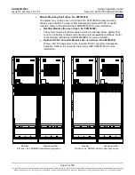
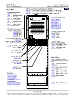
When the system is equipped with a List
, or
front access Input Termination
Assembly, refer to the restrictions under these list descriptions.
Will not accept List
converter interface components.
Will not accept dual voltage distribution panels.
Order maximum of one (1) List
is ordered. Order List 2 or List 5, not both.
Interbay power cabling is not included, and must be separately provided per site requirements.
If low voltage disconnect (List LL or List LB) is to be included, the Main Bay (List 1) of the system must also
have low voltage disconnect (List LL or List LB).
Ordering Notes
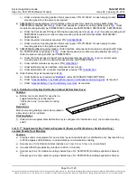
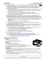
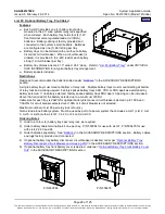
1) Order a relay rack or shipping brackets per “
Relay Racks and Shipping Brackets
” under ACCESSORY
DESCRIPTIONS. If required, order relay rack transition plates per “
Transition Plates to Mount Relay
Rack on Top of GNB Absolyte IIP Batteries
” under ACCESSORY DESCRIPTIONS.
, or
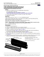
a) Order up to four (4) (per the capacity of the distribution cabinet ordered) distribution panels, battery
disconnect panels, and/or return bar panel as required per “
Single Voltage Distribution Panel
”,
Battery Disconnect Distribution Panel
” under LIST DESCRIPTIONS.
b) Order battery disconnect contactors and low voltage disconnect options as required per “
Low Voltage Disconnect Options
” under LIST DESCRIPTIONS.
c) Order fuses and/or circuit breakers as required per “
” under ACCESSORY
DESCRIPTIONS.
d) Order input and load distribution lugs, lug adapters, and lug hardware kits as required per “
” under ACCESSORY DESCRIPTIONS.
e) Order a distribution cabinet top shield as required per List
f) If distribution only, order a bottom rear distribution cabinet cover per List 4.
g) Order a battery shunt as required per List
, or
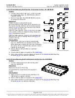
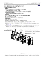
3) 588705000 Rectifier Option: Order interface components for module mounting shelf(s) Spec. No.
588705000 as required per List
. Order field expansion module mounting shelf(s) per List
. Order
module mounting shelf(s) per PD588705000 (choices are 58870500021, 58870500022, 58870500031,
58870500032).
a) Order the front access AC Input Termination Assembly per List
, or
58870500021 ordered (or order module mounting shelves with AC line cords or terminal blocks,
58870500022, 58870500031, 58870500032).
b) Order rectifier modules as required, P/N
, or
c) Order a module mounting position blank cover panel, P/N 21140440, for each empty module
mounting position in the system, as desired.
4) 588705000 Converter Option: Order interface components for module mounting shelf(s) Spec. No.
588705000 as required per List
. Order field expansion module mounting shelf(s) per List
. Order
module mounting shelf(s) per PD588705000 (choices are 58870500040, 58870500041, 58870500042).
a) Order the front access DC Input Termination Assembly per List
, or
58870500040 ordered (or order module mounting shelves with terminal blocks, 58870500041,
58870500042).
b) Order converter modules as required, P/N
c) Order a module mounting position blank cover panel, P/N 21140440, for each empty module
mounting position in the system, as desired.
5) 588705300 Rectifier/Converter Option: Order interface components for module mounting shelf(s) Spec.
No. 588705300 as required per List
. Order field expansion module mounting shelf(s) per List
Order module mounting shelf(s) per PD588705300.


