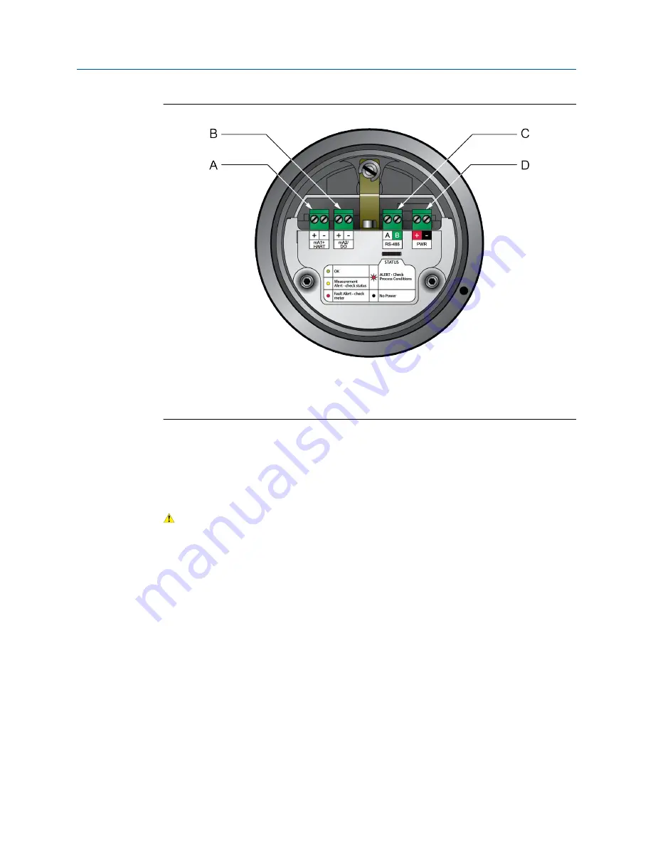
Transmitter outputs
Figure 3-1:
A.
Channel A (4-20 mA + HART)
B.
Channel B (4-20 mA)
C.
Channel C (RS-485)
D.
Power terminals
3.2
Wire power and outputs in a HART single-loop
environment
CAUTION!
Meter installation and wiring should be performed by suitably trained personnel only in
accordance with the applicable code of practice.
Procedure
Wire to the appropriate power and output terminals and pins (see
).
Wiring
Installation Manual
21


