background image

Maintenance

23

10.0 M

AINTENANCE

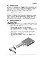
The Liebert UPStation GXT2U requires very little maintenance. The 

batteries are valve-regulated, nonspillable, lead acid and should be 

kept charged to obtain their designed life. The UPS continuously 

charges the batteries when connected to the mains supply.
When storing the UPS for any length of time, it is recommended to 

plug the UPS in for at least 24 hours every four to six months to 

ensure full recharge of the batteries.
The Liebert UPStation GXT2U is designed to allow the user to safely 

replace the internal batteries. Read the safety cautions before pro-

ceeding. Contact your local dealer or Liebert representative to obtain 

the appropriate replacement battery kit part number and pricing.

10.1 Battery Replacement

!

CAUTION

A battery can present a risk of electrical shock and high short 

circuit current. The following precautions should be observed 

before replacing the batteries:
• Remove rings, watches, or other metal objects.
• Use a Phillips (crosshead) screwdriver with insulated grips.
• Do not lay tools or other metal objects on top of the batteries.
• If the battery replacement kit is damaged in any way or 

shows signs of leakage, contact your local dealer or Liebert 

representative immediately. 

• Do not dispose of batteries in a fire. The batteries may 

explode.

Summary of Contents for Liebert UPStation GXT2U

Page 1: ...AC Power Systems For Business Critical Continuity Liebert UPStation GXT2U User Manual 230V 700 3000VA ...

Page 2: ......

Page 3: ...ss 6 5 0 INSTALLATION 8 5 1 Preparation 8 5 2 Tower UPS Installation 8 5 3 Rack Mount UPS Conversion and Installation 9 5 4 External Battery Cabinet Installation 13 6 0 CONTROLS AND INDICATORS 14 6 1 ON Alarm Silence Manual Battery Test Button 14 6 2 Standby Manual Bypass Button 15 6 3 Load Battery Level Indicators 4 Green 1 Amber 15 6 4 Fault Indicator LED Red 15 6 5 Bypass Indicator LED Amber 15...

Page 4: ...Mode Shutdown 20 8 3 1 Auto Enable Output 20 8 3 2 Pin 6 Logic 20 8 4 UPS Intelligent Communications 21 9 0 CONFIGURATION PROGRAM 22 9 1 Liebert UPStation GXT2U Configuration Program Abilities 22 9 1 1 What You Will Need 22 10 0 MAINTENANCE 23 10 1 Battery Replacement 23 10 1 1 Internal Battery Replacement Procedures 24 11 0 TROUBLESHOOTING 25 12 0 SPECIFICATIONS 30 12 1 Battery Cabinet Specificat...

Page 5: ...TROMAGNETIC COMPATIBILITY The Liebert UPStation GXT2U Series complies with the requirements of the EMC directive 2004 108 EC and the published technical standards Continued com pliance requires installation in accordance with these instructions and use of manufacturer approved accessories only Operate the UPS in an indoor environment only in an ambient tem perature range of 0 C to 40 C 32 F to 104...

Page 6: ...IREMENTS Never block or insert any object into the ventilation holes or other openings of the UPS DO NOT CONNECT equipment that could overload the UPS or demand half wave rectification from the UPS for example electric drills vacuum cleaners laser printers or hairdryers Storing magnetic media on top of the UPS may result in data loss or corruption Turn the UPS off and isolate the UPS before cleani...

Page 7: ...ock Indicates caution followed by important instructions AC input AC output Requests the user to consult the manual Indicates the unit contains a valve regulated lead acid battery Recycle DC voltage Equipment grounding conductor Bonded to ground AC voltage ON Standby i ...

Page 8: ... continuously conditions and regulates its output voltage whether mains power is present or not It supplies connected equip ment with clean sinewave power Sensitive electronic equipment oper ates best from sinewave power For ease of use the Liebert UPStation GXT2U features a light emit ting diode LED display to indicate either load percentage or battery capacity depending upon the mode of operatio...

Page 9: ...racting this sinewave input current achieves two objectives The mains power is used as efficiently as possible by the UPS The amount of distortion reflected on the mains is reduced This results in cleaner power being available to other devices in the building not being protected by the Liebert UPStation GXT2U 4 3 Inverter In normal operation the inverter utilizes the DC output of the power factor ...

Page 10: ... lead acid batteries To maintain battery design life operate the UPS in an ambient temperature of 20 C to 25 C 68 F to 77 F Optional external battery cabinets are available to extend battery run times 4 7 Dynamic Bypass The Liebert UPStation GXT2U provides an alternate path for mains power to the connected load in the unlikely event of a UPS malfunc tion Should the UPS have an overload overtempera...

Page 11: ...ure 1 Liebert UPStation GXT2U Rear View Rev USBCARD Circuit Protector Mains Input Cooling Fans USB card being fitted in Liebert IntelliSlot Port DB 9 Communications Port Output Sockets Support Base External Battery Connector ...

Page 12: ... GXT2U may be installed in either a tower configuration or in a rack depending on available space and use considerations Determine the type of installation and follow the appropriate instructions in either 5 2 Tower UPS Installation or 5 3 Rack Mount UPS Conversion and Installation 5 2 Tower UPS Installation When using the Liebert UPStation GXT2U in a tower configuration use the included support b...

Page 13: ... mounting hardware from the rack mounting kit P N RMKIT18 32 Bracket assemblies are interchangeable between left hand or right hand Remove inner member of each bracket assembly as shown at right by extending it to its outermost position depressing the retaining latch and then pulling inner member from bracket assembly NOTE When rack mounted the UPS must be supported by a shelf brackets or slide ra...

Page 14: ... rack mounting rails 4 Locate eight 8 M4 screws and eight 8 M4 nuts from hardware pack in this kit Each nut has a locking nylon insert that begins gripping the screw when it is halfway tight Make sure to tighten nut and screw completely to assure locking action Fasten rear member and front member together using four 4 screws and four 4 nuts per bracket assembly as shown in the figures below For ma...

Page 15: ...ent with inner members attached from Step 5 into bracket assemblies by inserting top and bottom edges of inner members into the top and bottom curved tracks of front members and sliding the equipment into rack see figure in Step 6 Ends of inner members are tapered to allow rear of the equipment to be angled upward before insertion if space allows Then the rear bottom edges of inner members can be ...

Page 16: ...ront panel overlays Remove the outer overlay used for tower installation This reveals a horizontally oriented front panel overlay for rack mounting Snap the front bezel back into place 10 Once the UPS is installed in the rack the load may be connected Ensure the load equipment is turned off plug all loads into the output sockets on the rear of the UPS 11 The input supply cable should be connected ...

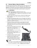
Page 17: ... local dealer or Liebert representative for these additional options and any assistance needed Fasten the slides into position with the screws per the instructions included with the slide rails 4 Use the enclosed support bases for the tower option to prevent tip over One additional set of support base extensions ships with each external battery cabinet 5 Connect the supplied external battery cabin...

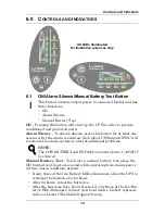
Page 18: ...activate the alarm system to alert of additional problems Manual Battery Test To initiate a manual battery test press the ON button for at least one second while operating from mains power with no alarm conditions present If only three of the five Battery LEDs illuminate allow the UPS to recharge the batteries for 24 hours After 24 hours retest the batteries After the batteries have been retested ...

Page 19: ... feature functions with Liebert MultiLink 3 software and can remotely initiate the battery test 6 4 Fault Indicator LED Red The Fault indicator LED is illuminated if the UPS has detected a problem Also one or more of the load battery level indicators may be illuminated refer to 11 0 Troubleshooting 6 5 Bypass Indicator LED Amber The Bypass indicator LED is illuminated when the UPS is operating fro...

Page 20: ...ble and is designed to allow selecting or changing the desired output voltage to match the mains via the Liebert UPStation GXT2U Configuration Program provided with the UPS The settings to choose from are 200 208 220 230 and 240 VAC output The factory default setting is 230 VAC CAUTION Never change the voltage settings while the UPS is ON and powering connected loads NOTE Setting output voltage to...

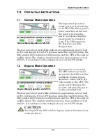
Page 21: ...e example above on the UPS output 7 2 Bypass Mode Operation Bypass mode occurs when the OFF button is pressed once while the UPS is in Nor mal Mode During bypass operation mains power pro vides energy to the UPS The mains power bypasses the inverter and provides power for the connected load The four green load level LEDs indicate an approximate level of load in 25 increments If the UPS becomes loa...

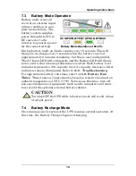
Page 22: ...em has occurred Each battery level indicator represents a 20 capacity level As capacity decreases fewer indicators remain illuminated Refer to 11 0 Troubleshooting For approximate battery run times refer to 13 0 Battery Run Times These times are approximates based on resistive load and an ambient temperature of 25 C 77 F To increase this time turn off non essential pieces of equipment such as idle...

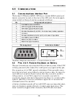
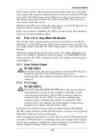
Page 23: ... unless the relay is used to switch a voltage source A 5 12 VDC signal for 1 5 seconds or greater is required to signal a shutdown Signals for less than 1 5 seconds will be ignored After Pin 4 receives a shutdown signal for 1 5 seconds the command cannot be canceled A battery shutdown signal on Pin 4 will NOT cause an immediate shut down A shutdown signal will start a 2 minute shutdown timer The t...

Page 24: ...ssed the UPS setting is read by the configuration program and displayed 8 3 1 Auto Enable Output 8 3 2 Pin 6 Logic If version 1 6 or later is used with an earlier Liebert UPStation GXT2U model with an earlier UPS firmware version the Any Mode Shutdown features cannot be changed If the configuration program is used with an earlier UPS model with an earlier UPS firmware version that does not support...

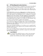
Page 25: ...Liebert IntelliSlot SNMP Web Card and Liebert MultiLink License Kits visit our Web site www liebert com or contact your local dealer or Liebert representative Several option cards are available for use in the Liebert IntelliSlot port of the Liebert UPStation GXT2U The Liebert IntelliSlot SNMP Web Card provides SNMP and Web based monitoring and control of the UPS across the network The Liebert Inte...

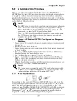
Page 26: ...ations reported by Liebert software products Modify the shutdown setting of DB 9 pin 6 for information on pin assignments see 8 0 Communications 9 1 1 What You Will Need In addition to the Liebert UPStation GXT2U UPS you will need the configuration program diskette and serial cable beige or tan 3 wire GND TX RX straight through 2 2 3 3 5 5 included in the UPS accessory box The BLACK ML9P9S CONTACT...

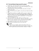
Page 27: ...l batteries Read the safety cautions before pro ceeding Contact your local dealer or Liebert representative to obtain the appropriate replacement battery kit part number and pricing 10 1 Battery Replacement CAUTION A battery can present a risk of electrical shock and high short circuit current The following precautions should be observed before replacing the batteries Remove rings watches or other...

Page 28: ...e new and old battery assemblies to make sure they are the same If so proceed with Step 6 otherwise STOP and contact your local dealer Liebert representative or the Liebert Worldwide Support Group 6 Line up and slide in the new replacement battery pack 7 Reconnect the two slotted battery connectors and gently push the battery wiring and battery pack assembly back into the UPS 8 Reattach the front ...

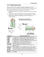
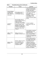
Page 29: ...sec B LED On bypass due to DC bus overvoltage beep every 4 sec C LED On bypass due to control power supply failure beep every 4 sec D LED On bypass due to PFC failure beep every 4 sec E LED On bypass due to inverter failure beep every 4 sec A C LEDs UPS failed battery test long beep every minute C E LEDs UPS shutdown due to command from communication port SNMP no beep Battery LED Flashing Internal...

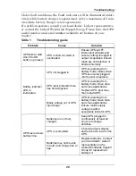
Page 30: ... internally Battery indicator LED is illuminated UPS not plugged in UPS is operating from battery mode make certain UPS is securely plugged into the wall receptacle UPS input protection fuse has blown opened UPS is operating from battery mode Save data and close applications Replace UPS input fuse then restart UPS Mains voltage out of UPS input range UPS is operating from battery mode Save data an...

Page 31: ... bus overvoltage UPS requires service Contact your local dealer Liebert representative or the Liebert Worldwide Support Group Fault and Bypass indicator LEDs and diagnostic LED C are illuminated UPS control power supply fault UPS requires service Contact your local dealer Liebert representative or the Liebert Worldwide Support Group Fault and Bypass indicator LEDs and diagnostic LED D are illumina...

Page 32: ...D will not start flashing even if the input wiring is changed Contact a qualified electrician to verify site wiring Battery LED is flashing Battery source is not available continuous horn Check battery connections completely power down and restart UPS NOTE If the battery circuit opens while the UPS is running it will be detected when the next battery test is performed Bypass LED is flashing Bypass...

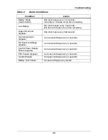
Page 33: ...tes of run time remaining Output Overload bypass One short beep every half second Overtemperature bypass A one second beep every 4 seconds DC Bus Overvoltage bypass A one second beep every 4 seconds Control Power Supply Failure bypass A one second beep every 4 seconds PFC Failure bypass A one second beep every 4 seconds Inverter Failure A one second beep every 4 seconds Battery Test Failure A 2 se...

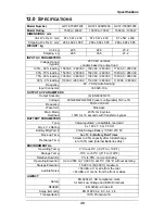
Page 34: ...200 208 220 230 240 user configurable VAC 3 Frequency 50 Hz or 60 Hz Waveform Sinewave Main Mode Overload 200 for 8 cycles 130 for 10 seconds with transfer to bypass BATTERY PARAMETERS Type Valve regulated nonspillable lead acid Qty x V x Rating 4 x 12V x 7 0 or 7 2 AH Battery Mfg Part China Storage Battery CSB 1270 F2 Back up Time See 13 0 Battery Run Times Recharge Time 5 Hours to 95 capacity af...

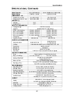
Page 35: ... Frequency 50 Hz or 60 Hz Waveform Sinewave Main Mode Overload 200 for 8 cycles 130 for 10 seconds with transfer to bypass BATTERY PARAMETERS Type Valve regulated nonspillable lead acid Qty x V x Rating 4 x 12V x 9 0 AH 6 x 12V x 9 0 AH Battery Mfg Part Panasonic UP VW1245P1 Yuasa REW 45 12 Back up Time See 13 0 Battery Run Times Recharge Time 5 Hours to 95 capacity after full discharge into 100 l...

Page 36: ... lead acid Qty x V x Rating 2 x 4 x 12V x 7 0 or 7 2 AH 2 x 6 x 12V x 9 0 AH Battery Mfg Part China Storage Battery CSB 1270 F2 Panasonic UP VW1234P1 Yuasa REW 45 12 Back up Time See 13 0 Battery Run Times ENVIRONMENTAL Operating Temp 0 C to 40 C 32 F to 104 F Storage Temp 15 C to 50 C 5 F to 122 F Relative Humidity 0 to 95 non condensing Operating Elevation Up to 3000 m 10 000 ft at 40 C 104 F wi...

Page 37: ...1 368 30 632 384 304 182 240 40 464 272 224 133 168 50 352 200 160 98 128 60 280 152 120 84 88 70 232 128 96 70 72 80 192 104 80 56 64 90 160 96 64 49 56 100 136 88 56 42 40 Internal Battery 3 External Battery Cabinets minutes 10 2976 2292 1728 560 1092 20 1380 1044 636 330 552 30 948 576 456 260 360 40 696 408 336 190 252 50 528 300 240 140 192 60 420 228 180 120 132 70 348 192 144 100 108 80 288...

Page 38: ...er for warranty protection Visit the Quick Links section of our Web site at http www liebert com Click on Product Warranty Registration and fill in the form If you have any questions please contact us at US 800 222 5877 Outside the US 614 841 6755 upstech liebert com ...

Page 39: ......

Page 40: ... 5841 257 Asia 7 F Dah Sing Financial Centre 108 Gloucester Road Wanchai Hong Kong 852 2572220 Fax 852 28029250 The global leader in enabling Business Critical Continuity Business Critical Continuity Emerson Network Power and the Emerson Network Power logo are trademarks and service marks of Emerson Electric Co 2007 Emerson Electric Co AC Power Systems Connectivity DC Power Systems Integrated Cabi...

Reviews: