


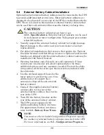


Communications
19
8.0
C
OMMUNICATIONS
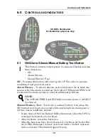
8.1
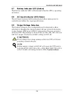
Communications Interface Port
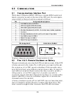
The Liebert UPStation GXT2U UPS has a standard DB-9 serial port
female connector located on the rear of the UPS unit. Several signals
are provided on this port and are assigned as follows:
* Maximum voltage and current on pins 1, 7, 8, and 9 is 60VDC; 10.0 mA.
8.2
Pins 4 & 5 - Remote Shutdown on Battery
This pin is functional only when the UPS is in battery mode. If the UPS
is being powered by the mains, Pin 4 will ignore any signal on this pin.
Pin 4 requires a 5-12 VDC signal to shutdown. This normally comes
form the serial port using Liebert’s contact closure cable. It cannot be
used with just a contact closure unless the relay is used to switch a
voltage source. A 5-12 VDC signal for 1.5 seconds or greater is
required to signal a shutdown. Signals for less than 1.5 seconds will be
ignored. After Pin 4 receives a shutdown signal for 1.5 seconds, the
command cannot be canceled.
A battery shutdown signal on Pin 4 will NOT cause an immediate shut-
down. A shutdown signal will start a 2-minute shutdown timer. The
timer cannot be stopped. After 2 minutes, the UPS will shut down.
Pin
Assignment Description
1
Low Battery (open collector)
2
UPS TxD (typical RS-232 levels)
3
UPS RxD (typical RS-232 levels)
4
Remote Shutdown (5-12VDC, 10-24 mA max); battery operation
5
Common
6
Remote Shutdown (short to pin 5); all modes of operation
7
Low Battery (open emitter)
8
Mains Fail (open emitter)
9
Mains Fail (open collector)
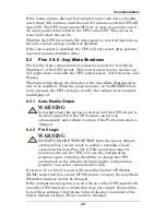
Pin Assignment
Collector to Emitter*
5
4
3
2
1
6
7
8
9
(-)
(+)
330 Ohms
Open
Collector
Open
Emitter


