background image

S600 Instruction Manual 

SERVICE

SERVICE

SERVICE

SERVICE

SERVICE

SERVICE

P154 IIO 2

1

14

2

15

3

16

8

20

9

21
10
22

20
21
22
23
24
25
26
27
28
29

31
32
33
34
35

36
37

37
36
35
34
33
32
31
30
29
28
27
26
25
24

5

0V

0V

SKT D

SKT E

SKT F

DIG OUT 1+

DIG OUT 4+

COMMON GND

DIG OUT 5+

DIG OUT 6+

DIG OUT 7+

DIG OUT 8+

COMMON GND

DIG OUT 9+

DIG OUT 10+

DIG OUT 11+

DIG OUT 12+

COMMON GND

PIM PULSE +

OUTPUT  -

17

5

18
26

4

11
23
12
13
19
24
25

1
2
3
4
5
6
7
8
9

10

13
14
15
16
17
18
19

19
18
17
16
15
14
13
12
11
10

9
8
7
4

23

3

22

2

21

1

20

HIT

HIT

SKT D

SKT E

SKT F

SWITCH 1 -

SWITCH 2 -

SWITCH 3 -

SWITCH 4 -

 VE

+ RAW PULSE

- OUTPUT

GND

GND

GND

GND

GND

DIG IN 17 -

DIG IN 18 -

DIG IN 19 -

DIG IN 20 -

 VE

DIG IN 5 -

DIG IN 6 -

DIG IN 7 -

DIG IN 8 -

 VE

DIG IN 9 -

DIG IN 10 -

DIG IN 11 -

DIG IN 12 -

 VE

DIG IN 13 -

DIG IN 14 -

DIG IN 15 -

DIG IN 16 -

 VE

+  DUAL PULSE
-

CHANNEL  1

+  DUAL PULSE
-

CHANNEL  2

+  DUAL PULSE
-

CHANNEL  3

+  DUAL PULSE
-

CHANNEL  4

+

DENSITY 1   

-

RAW PULSE +

INPUT 1 -

DIG OUT 2+

DIG OUT 3+

3K3

3K3

3K3

0V

LINKS

RAW PULSE +

INPUT 2 -

RAW PULSE +

INPUT 3 -

PIM LOOP +

INPUT  -

+

DENSITY 2   

-

DIG IN 25 -

DIG IN 26 -

DIG IN 27 -

DIG IN 28 -

 VE

DIG IN 29 -

DIG IN 30 -

DIG IN 31 -

DIG IN 32 -

 VE

PULSE OUT 1+

PULSE OUT 2+

PULSE OUT 3+

PULSE OUT 4+

COMMON GND

DIG IN 1 -

DIG IN 2 -

DIG IN 3 -

DIG IN 4 -

 VE

DIG IN 21 -

DIG IN 22 -

DIG IN 23 -

DIG IN 24 -

 VE

OV

OV

OV

+24V

+24V

PULSE OUT 2+

+24V

+24V

+24V

+24V

+24V

+24V

+24V


6

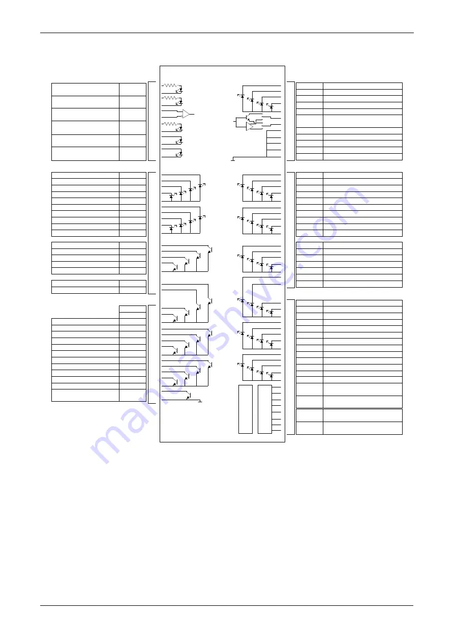
Figure 4-22. P154 Prover Board Terminations 

4.2.1  Digital Inputs (DIGIN) 

Each plug-in board has 32 optically-isolated digital inputs (DIGIN). 

The digital inputs have been grouped into four banks of 4-off single-

ended inputs with one common feed. 
The sample period is 500 milliseconds. 
The DIGIN channels use the SKT-E and SKT-F connectors located on 

the backplate of the P154 board. Refer to Tables 4-15 and 4-16 for the 

DIGIN pin connections.  

4-18 I/O 

Revised 

Jan-07 

Summary of Contents for FloBoss S600

Page 1: ...Remote Automation Solutions Form Number A6115 Part Number D301150X412 January 2007 FloBoss S600 Flow Manager Instruction Manual ...

Page 2: ...other marks are the property of their respective owners 2001 2007 Remote Automation Solutions division of Emerson Process Management All rights reserved Printed in the U S A www EmersonProcess com flow While this information is presented in good faith and believed to be accurate Emerson Process Management does not guarantee satisfactory results from reliance upon such information Nothing contained...

Page 3: ...2 CPU Board 3 1 3 2 Power Supply 3 3 3 2 1 Watchdog Relay 3 4 3 2 2 On Board Battery Backup 3 4 3 3 Communication Ports 3 5 3 3 1 EIA 232 RS 232 Serial Port 3 5 3 3 2 EIA 422 RS 422 EIA 485 RS 485 Multi drop Port 3 6 3 3 3 Ethernet LAN Port 3 7 3 3 4 Local Operator PC or Remote Display Port 3 7 3 4 CPU On Board Connectors 3 9 3 5 CPU Bit Links Jumpers 3 9 3 6 Dual Ethernet LAN Port 3 10 Chapter 4 ...

Page 4: ...to a Function F Key 5 10 5 7 6 Using the Exponential EXPT Key 5 11 5 7 7 Using the Print Key 5 12 Chapter 6 Webserver Access 6 1 6 1 Defining Webserver Access 6 2 6 2 Accessing the S600 6 2 6 3 Navigating the Webserver Interface 6 4 Chapter 7 Startup 7 1 7 1 Starting the S600 7 1 7 2 Warm Start 7 1 7 3 Cold Start 7 1 7 3 1 Initiating a Cold Start 7 2 7 4 Startup Menu 7 3 7 4 1 Network Setup 7 4 7 ...

Page 5: ...ix A Glossary A 1 Appendix B Front Panel Navigation B 1 B 1 Main Menu B 1 B 2 Flow Rates Menu B 2 B 3 Totals Menu B 2 B 4 Operator Menu B 3 B 5 Plant I O Menu B 4 B 6 System Settings Menu B 4 B 7 Tech Engineer Menu B 5 B 8 Calculations Menu B 6 Index I 1 ...

Page 6: ...vi Revised Jan 07 ...

Page 7: ...anel mounting procedures This chapter also describes the installation and removal of the plug in boards Chapter 3 CPU Describes the use of the communications and power connector blocks field wiring configurations and bit link settings for the plug in CPU board as well as the second Ethernet communications port Chapter 4 Input Output I O Describes the use of the plug in connector blocks field wirin...

Page 8: ... a stand alone flow computer or as a system component The intelligent I O boards fit both gas and liquid applications and support two streams and a header Adding I O boards up to a maximum of three allows you to configure up to six streams and two headers The S600 supports orifice ultrasonic turbine positive displacement Coriolis Annubar and V Cone flow meter types and Master Meter small volume co...

Page 9: ...e S600 uses distributed processing to achieve maximum performance The main CPU incorporates a hardware floating point processor Each additional card also has local processing to convert inputs and output from engineering units to field values and vice versa as well as running background tests and PID loops All metering calculations are performed using 64 bit double precision floating point numbers...

Page 10: ... you can both send upload new or modified configurations to the S600 and receive download existing configurations from the S600 With the Config600 software you can define the following functions with the S600 Stream and station totalisation Batch totalisation and correction Three term PID control Flow balancing Flow scheduling Automatic proving sequence K factor linearization Valve monitor control...

Page 11: ...g600 Lite Use the Config600 Lite software editor suite to modify pre developed configurations transfer existing configurations edit items on the front panel display and customize reports Note Config600 Lite is typically used to custom configure a new S600 during installation With Config600 Lite you can Edit initialization process data including orifice size analog input scaling alarm limits and ke...

Page 12: ... and edit custom reports With Config600 Pro you can Create a new application from base templates for gas liquid and prover applications Edit process configuration data including orifice size analog input scaling alarm limits and keypad values Build and customize Modbus slave maps Modbus master polling sequences front panel displays and period report formats Specify the engineering units and totali...

Page 13: ...f good workmanship Although the S600 shipped to you may not include all of the hardware options described in this manual the procedure for the basic installation of the unit remains the same Note We strongly recommend you familiarize yourself with the procedures described in this chapter before you begin to install the S600 The S600 uses a modular design that provides maximum flexibility and ease ...

Page 14: ...ial attention to the combined heating effect This combined heat could increase the environmental temperature beyond its acceptable threshold thereby impacting performance 2 3 Required Tools for Installation Before you attempt to install the S600 ensure that you have the following tools Small flat blade screwdriver suitable for the slot headed captive screws on the rear of the case that secure each...

Page 15: ...e confident that all parts are working correctly 2 4 2 Removing the Front Panel To begin the mounting process remove the front panel from the S600 1 Ensure power has been removed from the S600 2 Using a 2 5 mm Allen key remove the hex cap screw from the bottom center of the front panel refer to Figure 2 2 Figure 2 2 Removing the Front Panel 3 Carefully slide the front panel up 4 mm 0 15 in to allo...

Page 16: ...of the connector with its mating keyway You must correctly re insert the ribbon cable at the end of the installation process Caution Do not remove the ribbon cable from the S600 housing entrance This might damage the S600 Disconnect Here Figure 2 4 Remove Connector 5 Remove the top and bottom bosses from the unit housing using a 5 5 mm 5 BA hex wrench 2 4 Installation Revised Jan 07 ...

Page 17: ...ntenance Figure 2 5 Panel Mount Dimensions 2 4 3 Installing the Panel Mounted Unit After removing the front panel install the panel mounted unit 1 Keeping environmental considerations in mind construct the framework of the cubicle to support the operating panel Note A standard 483 mm 19 in rack that is 311 mm 12 25 in high can accommodate up to four S600s with the rear of the case supported 2 Refe...

Page 18: ...ure a panel thickness of at least 3 mm 0 12 in to prevent distortion If you use a thinner panel support the rear of the case refer to Figure 2 7 Caution Always use a rear support or anchor to prevent twisting and other distortion effects during installation and maintenance Figure 2 7 Panel Mount Support 2 6 Installation Revised Jan 07 ...

Page 19: ...nger tight Turn an additional 180 degrees clockwise to complete the installation Caution Do not over tighten the screw Over tightening will damage the panel face 2 5 Installing and Removing the Boards The S600 ships with the boards already installed Follow this procedure if you need to remove the boards for maintenance or upgrade purposes The CPU board is located in the left most rear slot of the ...

Page 20: ...Retention Screws 3 Unlatch the ejectors for the appropriate board and pull the board clear of the case You may need to rock the board slightly to release the connectors refer to Figures 2 9 and 2 10 Figure 2 9 Using the Ejectors 2 8 Installation Revised Jan 07 ...

Page 21: ...e until it mates fully with the appropriate connector on the backplane 2 Press each of the two ejectors securely into place once the board is fully inserted Caution Inserting and locating a plug in board along the guides does not require excessive force Take care not to twist or otherwise distort the boards during the installation 3 Secure the board with the retention screws two per board Revised ...

Page 22: ...S600 Instruction Manual 2 10 Installation Revised Jan 07 ...

Page 23: ...e heart of the S600 system Various plug in connections are provided on the rear backplate of the CPU board Refer to Figure 3 1 for an illustration of the P152 CPU board backplate and to Figure 3 2 for a schematic of the CPU power terminations The board uses additional connectors and bit links jumpers which are set at the factory prior to shipping It is recommended that all wiring be made with stra...

Page 24: ...S600 Instruction Manual TB 1 Power COM 1 2 COM 3 COM 4 Remote I O TB 2 COM 5 6 7 RS 232 RS 485 Network Figure 3 1 P152 CPU Backplate Figure 3 2 P152 CPU Board 3 2 CPU Revised Jan 07 ...

Page 25: ...7 8 1 2 3 4 5 6 7 8 9 10 11 12 13 14 15 0V RS232 COMM 3 RJ45 0V RS232 SIG GND DTR RTS TX RX CTS DSR DCD LCD AND SETUP 24v 15v GND 24V DC SUPPLY 24V DC INPUT DC OUTPUT WATCH DOG RS232 RS232 SERVICE LCD SETUP ETHERNET RS485 PORT 8 PORT 5 PORT 6 PORT 7 COMPUTER ALARM COMMS TO P144 I O BOARDS RESERVED FOR FRONT PANEL AND CONFIG 600 COMMS RS422 OR RS485 RS422 OR RS485 Figure 3 3 P152 CPU Terminations 3...

Page 26: ...ndard 5 mm pitch screw terminals The relay is energized during normal operation A CPU failure causes the relay to de energize The watchdog period is 2 5 seconds maximum Note Contact is rated at 1 Amp 30 Volts dc and 30 Volts ac and is a Form C contact Table 3 2 TB 1 Pin Connections Watchdog Relay Pin Function 6 Normally Closed 7 Common 8 Normally Open 3 2 2 On Board Battery Backup The battery back...

Page 27: ...Comm 1 COM1 2 Internal Connection to Front Panel Keypad Comm 2 COM1 2 Config600 IPL 600 Comm 3 COM3 EIA 232 RS 232 Comm 4 COM4 EIA 232 RS 232 Comm 5 6 7 TB2 EIA 422 RS 422 or EIA 485 RS 485 Comm 8 Remote I O External Reserved for future use and Internal Connection to I O Boards Comm 9 Network Ethernet For information on the communications port on the front panel which can also act as Comm 2 refer ...

Page 28: ... recommended especially in noisy environments that you connect the cable screen to protective earth to keep the signal ground separate 3 3 2 EIA 422 RS 422 EIA 485 RS 485 Multi drop Port Three EIA 422 RS 422 or EIA 485 RS 485 ports are located on the P152 CPU board These provide high speed long distance links of up to 38400 bps and 1200 m 4000 ft The ports use the connector labeled TB 2 which is C...

Page 29: ... this communications port Note For information on the optional second Ethernet port refer to Section 3 6 Dual Ethernet LAN Port 3 3 4 Local Operator PC or Remote Display Port Use the connector labeled COM1 2 on the P152 CPU board s backplate to connect the S600 to a remote display COM1 or the host PC COM2 Do not modify the COM1 2 port for other functions The COM1 2 port uses a standard 15 way D ty...

Page 30: ...ting to the S600 A special serial cable is required to connect the host PC to the FloBoss S600 unit A ready made link cable is available for a PC with a 9 pin serial port Alternatively you may fabricate your own link cable using the wiring details in Figure 3 4 Note Due to the high baud rate used for the communications between the host PC and the S600 restrict the maximum cable length to 5 m 15 ft...

Page 31: ... 3 9 shows the CPU bit links or jumpers This information is for identification purposes only Do not modify these settings unless told to do so by the factory Note The position values shown in boldface are the default configuration settings which may not apply to your specific configuration Table 3 9 CPU Bit Links Jumper Link Position Description LK1 LK2 Not Used CPU RADISYS LK3 ON OFF Voltage Sele...

Page 32: ...hen 22 23 ON 50 MHz When 22 OFF 23 ON 66 MHz Ethernet LK24 ON OFF ENEEP LK25 ON OFF I O Select 2 LK26 ON OFF I O Select 1 LK27 ON OFF I O Select 0 Cache Select LK28 ON OFF Non Enhanced Off LK is On or Enhanced On Writethrough Off Writeback LK is Off LK29 ON OFF Link when write back processor fitted LK30 Not Used 3 6 Dual Ethernet LAN Port The optional P190 second Ethernet port on the S600 is for h...

Page 33: ...quired For field installation the second Ethernet board is provided with a specialized backplate Note Before you use this port verify the IP settings of the port on the front panel From the Startup menu select Network Setup Network I F 2 If no addresses have been assigned you must assign them Exercise caution Network I F 1 and Network I F 2 must each have different subnet masks Revised Jan 07 CPU ...

Page 34: ...S600 Instruction Manual 3 12 CPU Revised Jan 07 ...

Page 35: ...er Bit Links Jumpers 4 24 4 3 P188 HART Board 4 25 Perform all wiring with stranded wire no larger than 1 75mm2 Observe all local wiring practices and regulations Caution Do not use a Mega or similar instrument to check for isolation or continuity between signals on any of the S600 connectors These instruments produce voltages far in excess of design parameters and may damage the S600 4 1 P144 I O...

Page 36: ... SKT A ANIN 1 10 ANOUT 1 4 SKT B ANIN 11 12 DIGIN 1 6 DIGOUT 1 2 Freq Inputs Pulse Outputs SKT C DIGIN 7 16 DIGOUT 3 12 Turbine Inputs Figure 4 1 Backplate with P144 I O Board Figure 4 2 P144 I O Board 4 2 I O Revised Jan 07 ...

Page 37: ...T 7 DIG OUT 8 COMMON GND DIG OUT 9 DIG OUT 10 DIG OUT 11 DIG OUT 12 COMMON GND DUAL PULSE CHANNEL 1 DUAL PULSE CHANNEL 2 DUAL PULSE CHANNEL 3 DUAL PULSE CHANNEL 4 SUPPLY DAC 4 OUTPUT GROUND SUPPLY DAC 3 OUTPUT GROUND SUPPLY DAC 1 OUTPUT GROUND SUPPLY DAC 2 OUTPUT GROUND I PRT 1 V INPUT V I I PRT 2 V INPUT V I I PRT 3 V INPUT V I DIG IN 1 DIG IN 2 DIG IN 3 DIG IN 4 DIG IN 6 DIG IN 7 SERVICE SERVICE...

Page 38: ... 10 on the second A D converter for either voltage or current Refer to Table 4 13 for P144 I O Bit Link settings Figure 4 4 Analogue Input Schematic with IS Barrier and using Internal Resistor Figure 4 5 Analogue Input Schematic without IS Barrier and using External Resistor The ANIN channels use the connectors labeled SKT A and SKT B which are located on the backplate of the P144 board Channels C...

Page 39: ...supports four analogue outputs D A Converter Each D A Converter channel is fully floating and provides its own floating supply Loads of up to a 650 ohm loop impedance can be connected directly The unit can be used in either source or sink configuration Refer to Figures 4 6 4 7 and 4 8 The D A Converter output channels use the connector labeled SKT A which is located on the backplate of the P144 bo...

Page 40: ...1 3 Digital Inputs DIGIN Each plug in board provides 16 optically isolated digital inputs DIGIN The digital inputs have been grouped into four banks of 4 off single ended inputs with one common feed Refer to Figures 4 9 and 4 10 The sample period is 500 milliseconds The DIGIN channels use the connectors labeled SKT B and SKT C which are located on the backplate of the P144 board Refer to Tables 4 ...

Page 41: ...in Function 13 DIGIN CH1 14 DIGIN CH2 15 DIGIN CH3 16 DIGIN CH4 17 RETURN CH1 4 18 DIGIN CH5 19 DIGIN CH6 Table 4 5 DIGIN Pin Connections for SKT C Pin Function 19 DIGIN CH7 18 DIGIN CH8 17 RETURN CH5 8 16 DIGIN CH9 15 DIGIN CH10 14 DIGIN CH11 13 DIGIN CH12 12 RETURN CH9 12 11 DIGIN CH13 10 DIGIN CH14 9 DIGIN CH15 8 DIGIN CH16 7 RETURN CH13 16 Revised Jan 07 I O 4 7 ...

Page 42: ...ies with the load When using inductive loads such as relay coils place a diode across the load Refer to Figures 4 11 and 4 12 The DIGOUT channels use the connectors labeled SKT B and SKT C which are located on the backplate of the P144 board Refer to Tables 4 6 and 4 7 for the DIGOUT pin connections Figure 4 11 Digital Output Schematic Relay Figure 4 12 Digital Output Schematic 24 V Switched Indic...

Page 43: ...ut range of 1 to 10 KHz Each channel has live integrity checking If cabling faults develop or if the pre amp power fails the software activates a configurable circuit fail alarm The electrical connection for these inputs depends on which DPR mezzanine card is fitted to the P144 I O module The dual mezzanine card accepts pulse inputs from 3 5 Volts dc to 24 Volts dc when wired as show in Figures 4 ...

Page 44: ...ULSE CH2 22 SINGLE DUAL PULSE CH2 2 SINGLE DUAL PULSE CH3 21 SINGLE DUAL PULSE CH3 1 SINGLE DUAL PULSE CH4 20 SINGLE DUAL PULSE CH4 4 1 6 Pulse Outputs PULSEOUT The system supports five programmable pulse output channels PULSEOUT which are typically used for electronic counters or sampler control Refer to Figure 4 15 Table 4 9 shows the PULSEOUT pin connections Figure 4 15 Pulse Output Schematic 4...

Page 45: ...0 supports a single raw pulse output typically used in prover applications to mimic the turbine signals and send them to the prover mezzanine card Refer to Figure 4 16 A 1K ohm resistor is required if the pulse rate on the prover bus exceeds 1 KHz if there are more than three S600s or if more than 20 m of cable is required Table 4 10 shows the RAWOUT pin connections Figure 4 16 Raw Pulse Output Sc...

Page 46: ...nput range of 0 to 10 KHz Bit links are provided to allow the inputs to be AC or DC coupled Refer to Figures 4 17 and 4 18 The frequency input channels use the SKT B connector which is located on the backplate of the P144 board Table 4 11 shows the frequency input pin connections Figure 4 17 Frequency Input Schematic with IS Barrier and AC Coupled Figure 4 18 Frequency Input Schematic without IS B...

Page 47: ... 392 F The S600 supports three styles of PRT RTD probes DIN coefficient of 0 00385 ohm ohms degrees Celsius American Standard coefficient of 0 003926 ohm ohms degrees Centigrade Calendar Van Dusen equations The DIN 43760 selection is typical in Europe and common in the United States while the American Standard selection coefficient alpha is still common for circumstances where a slightly purer pla...

Page 48: ...26 PRT CH3 I 4 1 10 P144 I O Bit Links Jumpers The boldface entries in the Position column on Table 4 13 are the default configuration settings These may not apply to your specific configuration Do not change the bit link settings unless told to do so by the factory Note Point to point communications for the P144 I O board require Link 2 to be ON Multiplex MUX communications require Link 2 to be O...

Page 49: ...ode OFF ADC CH4 Voltage Mode LK201 ON ADC CH5 Current Mode OFF ADC CH5 Voltage Mode LK211 ON ADC CH6 Current Mode OFF ADC CH6 Voltage Mode LK221 ON ADC CH7 Current Mode OFF ADC CH7 Voltage Mode LK231 ON ADC CH8 Current Mode OFF ADC CH8 Voltage Mode LK241 ON ADC CH9 Current Mode OFF ADC CH9 Voltage Mode LK251 ON ADC CH10 Current Mode OFF ADC CH10 Voltage Mode LK26 LK27 LK28 Cannot be changed LK29 L...

Page 50: ...F OFF OFF OFF 2 3 4 2 P154 Prover Board The P154 dedicated prover interface card has been designed to work with compact or small volume provers unidirectional provers bi directional provers and Master Meter provers having one two or four detector switches The P154 board contains high resolution timing circuits which enable you to use dual chronometry methods These increase the apparent resolution ...

Page 51: ... 3 DENSITY 1 2 SKT E DIGIN 1 6 AND 17 32 DIGOUT 1 2 Pulse Outputs 1 4 DIGIN 7 16 DIGOUT 3 12 DUAL PULSE 1 4 SPHERE SWITCH 1 4 PLLIN RA WOUT PLLOUT Figure 4 20 Backplate with P154 Prover Board Figure 4 21 P154 Prover Board Revised Jan 07 I O 4 17 ...

Page 52: ...IG IN 16 COMMON VE DUAL PULSE CHANNEL 1 DUAL PULSE CHANNEL 2 DUAL PULSE CHANNEL 3 DUAL PULSE CHANNEL 4 DENSITY 1 RAW PULSE INPUT 1 DIG OUT 2 DIG OUT 3 3K3 3K3 3K3 0V LINKS RAW PULSE INPUT 2 RAW PULSE INPUT 3 PIM LOOP INPUT DENSITY 2 DIG IN 25 DIG IN 26 DIG IN 27 DIG IN 28 COMMON VE DIG IN 29 DIG IN 30 DIG IN 31 DIG IN 32 COMMON VE PULSE OUT 1 PULSE OUT 2 PULSE OUT 3 PULSE OUT 4 COMMON GND DIG IN 1...

Page 53: ...put Schematic Open Collector Device Figure 4 24 Digital Input Schematic Relay Table 4 15 DIGIN Pin Connections for SKT E Pin Function 13 DIGIN CH1 14 DIGIN CH2 15 DIGIN CH3 16 DIGIN CH4 17 RETURN CH1 4 18 DIGIN CH5 19 DIGIN CH6 1 DIGIN CH 17 2 DIGIN CH 18 3 DIGIN CH 19 4 DIGIN CH 20 5 RETURN CH 17 20 6 DIGIN CH 21 7 DIGIN CH 22 8 DIGIN CH 23 9 DIGIN CH 24 10 RETURN CH 21 24 20 DIGIN CH 25 21 DIGIN...

Page 54: ...oard provides 12 digital output DIGOUT high current open collector type channels The maximum current rating is 100 mAmps at 24 Volts dc Output frequencies up to 0 5 Hz are possible Carefully check the DC polarity Use an external DC supply in series with the load When using inductive loads such as relay coils place a diode across the load The DIGOUT channels CH1 and CH2 are located on connector SKT...

Page 55: ...11 26 DIGOUT CH12 25 RETURN CH9 12 4 2 3 Turbine Pulse Inputs You can use the four pulse inputs either independently or as two pairs Generally they are used for dual pulse measurement such as turbine applications In dual pulse mode you can enable level A or B pulse checking Each input has an input range of 1 to 10 KHz Each channel has live integrity checking If cabling faults develop or if the pre...

Page 56: ...00 provides four programmable pulse outputs typically used for electronic counters Refer to Table 4 20 for the PULSEOUT pin connections Refer to Figure 4 28 for field wiring schematics Figure 4 28 Pulse Output Schematic Table 4 20 PULSEOUT Pin Connections for SKT E Pin Function 31 PULSEOUT CH1 32 PULSEOUT CH2 33 PULSEOUT CH3 34 PULSEOUT CH4 35 RETURN CH1 4 4 2 5 Frequency Inputs The S600 supports ...

Page 57: ...d wiring schematics Figure 4 29 Frequency Input Schematic with IS Barrier and AC Coupled Figure 4 30 Frequency Input Schematic without IS Barrier and DC Coupled Table 4 21 Frequency Input Pin Connections for SKT D Pin Function 9 FREQUENCY CH1 21 FREQUENCY CH1 10 FREQUENCY CH2 22 FREQUENCY CH2 Revised Jan 07 I O 4 23 ...

Page 58: ...plexed mode MUX MUX Address 1 2 3 4 5 6 7 8 9 10 11 12 13 14 15 LK3 LK4 LK5 LK6 LK7 LK8 LK9 LK10 1 2 2 3 Altera Voltage LK12 1 2 3 465V 2 3 5V Vcc Raw Pulse Output Mode currently not supported LK13 14 1 2 RS 422 differential driver 2 3 Open collector Raw Pulse Input 3 Line Determination LK15 16 ON Line determination resistors connected ve pulled up to Vcc and ve down to 0V OFF Lines undetermined T...

Page 59: ... socket B connects to a 25 pin female connector Refer to Tables 4 24 and 4 25 Refer to Figures 4 31 through 33 for field wiring information Table 4 24 P188 HART Pin Connections Socket A Socket A Channel Number Socket A Pin Number Channel 1 1 Channel 1 14 Channel 2 2 Channel 2 15 Channel 3 3 Channel 3 16 Channel 4 4 Channel 4 17 Channel 5 5 Channel 5 18 Channel 6 6 Channel 6 19 Channel 7 7 Channel ...

Page 60: ...uction Manual Figure 4 31 HART Device Beyond the IS Barrier Figure 4 32 HART Device and Hand Held Communicator Beyond the IS Barrier Figure 4 33 HART Device without Hand Held Communicator 4 26 I O Revised Jan 07 ...

Page 61: ... Display 5 5 5 6 Navigating the Display 5 7 5 7 Entering Data 5 8 5 7 1 Security Codes 5 8 5 7 2 Changing a Displayed Value 5 8 5 7 3 Changing a Calculation Mode 5 9 5 7 4 Assigning a Default Page 5 10 5 7 5 Assigning a Page to a Function F Key 5 10 5 7 6 Using the Exponential EXPT Key 5 11 5 7 7 Using the Print Key 5 12 5 1 Description The S600 s front panel provides a local interface you can use...

Page 62: ...n using the 15 way D type female connector Table 5 1 Front Panel Port Connections Pin Function 1 RTS 2 TX 3 GND 4 GND 5 RX 6 CTS Figure 5 2 Front Panel Port Connector 5 3 Keypad The keypad for the front panel has been designed for ease of use and to reduce the possibility of error Keys on the keypad are color coded by type Yellow Function Dark green Four direction MENU Light green Numeric Dark gre...

Page 63: ... Refer to Section 5 7 4 for further information 5 3 4 Operation Keys You use the Operation keys in conjunction with the numeric keys to perform a variety of tasks including Exponent EXPT Use the EXPT key to enter numbers in scientific notation For example if the value you need to enter exceeds the space available on the display a maximum of 20 characters you need to express the data in exponential...

Page 64: ...larm the LED light is a constant red until you clear all the alarm conditions Alarm Display The first line of the alarm display indicates the date and time of the alarm Until you accept the alarm the date displays in inverse video The second and third lines describe where the alarm has been activated and its nature The total number of alarms both accepted and unaccepted appears on the bottom line ...

Page 65: ...atabase along with the associated text units and description Which data items you can modify depends upon the database configuration An asterisk at the end of a display line indicates a changeable Read Writable data item Prompts and messages appear when you enter or edit data items Display lines without asterisks are Read Only Status ID Line The Status ID line appears on the bottom of every data d...

Page 66: ...hand side of the Status ID line indicates the S600 mode Code S600 Status P Prover mode M Maintenance mode S Standby peer to peer communication link D Duty peer to peer communication link W Webserver locks out front panel access 5 6 Front Panel Revised Jan 07 ...

Page 67: ...te backspace key when entering or changing data Use and to move from the data display pages of one menu item to the data display pages of the previous or next menu item Accessing a Data Page Another way to access a specific data page is to use the DISP key and the data page s unique address That address appears in the Status ID line for that data display page For example you want to access the dat...

Page 68: ...nfiguration certain essential data entry fields require confirmation Note While in Change mode you can use to delete digits or characters by backspacing over the displayed data You can also press CLEAR at any time to abort the current operation or task 5 7 1 Security Codes Some operations at the front panel display require that you enter a security code Use the password assigned to you for your ac...

Page 69: ...key it 6 When the Enter New Value prompt displays key in the new value using integer numeric or scientific notation as appropriate The current value and any associated entry limits for this parameter also display Note If necessary you can edit the new data as you key it in Press CHNG and use to delete single figures or characters To abort the change press CLEAR 7 Press Enter to confirm and apply y...

Page 70: ...exits the edit sequence when you either accept or reject the value change 5 7 4 Assigning a Default Page If you have a specific activity to perform that requires you to temporarily use a particular menu or data display page use this procedure to set that menu or data display page as the temporary default S600 display To define the default display using the Minus key 1 Go to the required data displ...

Page 71: ...not display the value as a normal number Using the Config600 software you can force a data value to always display in scientific notation For further information refer either to the Config600 Pro Software User Manual Form A6169 or to the on line help for the Config600 software To enter an exponential value 1 Key in a value 2 Press EXPT an E appears on the display and then enter the required power ...

Page 72: ...arm system on this configuration Current Report Lists the current report as configured normally this would consist of the meter run totals Config Report Lists the configuration specific parameters including any configured installed calculation sets Archived Reports Lists all archived reports sorted by time and date Current Alarms Lists all the acknowledged and un acknowledged alarms currently set ...

Page 73: ...rts Reports 1 Current Report 2 Config Report 3 Archived Reports Communications 1 Modbus Maps Current Alarms No sub options prints a list of current alarms to the designated terminal or serial printer Logs 1 Alarm Log 2 Event Log Abort Printing No sub options stops printing ...

Page 74: ...S600 Instruction Manual 5 14 Front Panel Revised Jan 07 ...

Page 75: ...sing any personal computer PC with Internet access and Microsoft Windows Internet Explorer Version 6 0 or greater installed you can access the S600 over its Ethernet communications ports The S600 must have VxWorks firmware version 04 01 or greater installed and the configuration file residing on the S600 must have been created using Config600 software version 1 4 or greater Note Alternate web brow...

Page 76: ... only one control point Control is based on first access whether you connect through the S600 s front panel display or through a TCP IP connection Only the user with control may change data All other users regardless of access method can only view data until the first user logs off Once the first user logs off the S600 passes control to the next user with sufficient security who requests that writ...

Page 77: ...swords are established in the configuration If you are unsure of your user name or password check with the person who created the configuration for your application Note The security level assigned to your security code determines how many options are available on the web access interface See Figure 6 1 5 Click OK The browser opens displaying information from the S600 Figure 6 2 Initial Webserver ...

Page 78: ...een of data points to view Menu Bar CSV Button Hierarchy Menu Figure 6 3 Alarm Archive Report CSV Button The S600 web interface typically displays content as a text file as shown in Figure 6 3 You may be able to print the screen content using the PRINT button on the menu bar according to your defined authority Alternately various screens provide a button you can use to create a comma separated var...

Page 79: ...ta Menu on Prover I O Screen Some of the screens allow you to interact with the S600 If the text appears in bold you can change the data If the text appears in red the object is in an alarm state The system sends any modifications you make to a screen to the S600 as you make them Revised Jan 07 Webserver Access 6 5 ...

Page 80: ...hierarchy menu To close the webserver access link select the Log Off option in the menu bar and close the browser Caution The caching mechanism on many Internet browser applications may present a security challenge Remember to log out of your browser session which clears the browser s cache of S600 details 6 6 Webserver Access Revised Jan 07 ...

Page 81: ...ves any current accumulated values During a warm start the S600 displays the message RESTARTING Following a successful warm start the S600 Main menu displays which is the starting point for the display screens Refer to Chapter 5 Front Panel for more information on navigating the display screens If the S600 cannot find a valid configuration it does not perform a warm start Instead it displays the S...

Page 82: ...need it Otherwise an unplanned restart could result in lost data 1 Select the COLD START option from the Startup menu see Figure 7 1 2 Press 1 to keep or 2 to reset the totals 3 Press 1 to confirm the selection The S600 displays the message CONFIGURING PLEASE WAIT The S600 builds a new database using the configuration files held in Flash memory When completed the S600 Main menu displays Powered Co...

Page 83: ... 4 REFLASH FIRMWARE 8 FACTORY SETUP Figure 7 1 Startup Menu Startup menu options include If the S600 completes its start up initialization sequence but does not automatically warm start the S600 Startup menu displays see Figure 7 1 Option Description Warm Start Restarts a previously configured S600 at the point prior to being powered down Cold Start Builds a new metering database on the S600 using...

Page 84: ...ernet LAN network address 1 Select NETWORK SETUP from the Startup menu 2 Select either NETWORK I F 1 for the standard Ethernet port or NETWORK I F 2 for the Dual Ethernet port Note The options for TCP IP address and Subnet mask are valid for I F 1 and I F 2 The Gateway address is available only on I F 1 If the second network card P190 is installed I F 1 and I F 2 must each use separate subnets 3 S...

Page 85: ...COND ETHERNET CARD NOT PRESENT You are attempting to set up a second Ethernet card which is not physically installed To resolve Install a dual Ethernet board if required Note Most applications do not need this feature INCOMPATIBLE PC SETUP VERSION The configuration file has been edited using a version of Config600 that is incompatible with the version of firmware on the S600 To resolve Identify an...

Page 86: ...ort centre for further directions REPORT CONFIG HAS CHANGED COLD START REQUIRED This normally occurs when the report layout has been changed To resolve Initiate a cold start on the S600 or download the original config prior to report changes ERROR LOADING REPORT TEMPLATES S600 has encountered an error when reading the report templates To resolve Check reports for errors If you don t find errors co...

Page 87: ...8 8 8 1 Guidelines When you are attempting to diagnose a problem with an S600 Remember to write down what steps you have taken Note the order in which you remove components Note the orientation of the components before you modify or remove them Read and follow all Cautions in this manual Before you contact your local sales representative or technical support with a problem first check the followin...

Page 88: ...rt position then move it into the open warm start position to allow a warm start This also allows the unit to bypass the Startup menu in the future Check for a valid configuration If no configuration is present refer to Section 8 3 2 Send and Reflash Config File Check whether a Clear SRAM command has been issued Note If the S600 displays RESETTING for more than 2 minutes the Flash memory has faile...

Page 89: ...elect TECH ENGINEER COMMUNICATIONS SERIAL PORTS PORT 8 8 2 6 I O Fail Messages If the front panel displays an I O Fail message Check the bit link settings on the I O boards Check the I O field wiring connections Check that the I O boards are seated and secured 8 2 7 Serial Communications If you are experiencing troubles with a serial communications connection EIA 232 EIA 422 or EIA 485 Check to ma...

Page 90: ...he Config600 software select the required vxworks bin file and click Send Now to download it to the S600 5 The following message displays on the front panel RECEIVING BINARY FILE Once the S600 has successfully downloaded the file the following message displays on the front panel RECEIVED OK Note Do not proceed if the front panel displays the message FLASH FAILED Remove the power connector for 5 se...

Page 91: ...from factory personnel in the event of a problem Use Clear SRAM to overwrite the S600 s SRAM area With this option you lose all battery backed configuration data including system configuration data process configuration data metering totalizers and network settings Following a Clear SRAM command the S600 restarts and redisplays the Startup menu You cannot warm start the S600 again until you downlo...

Page 92: ...module from the S600 case 3 Remove the fuse using only light pressure 4 Check the integrity of the fuse If necessary replace it only with a 20 mm x 5 mm 2 5 Amp anti surge fuse Note Using a fuse with a higher current rating invalidates the S600 warranty 5 Replace the fuse checking to be sure it is secure 6 Replace the CPU module into the case 7 Replace the plug connectors 8 Switch on the power sup...

Page 93: ...K13 LK14 displays 7 Power down the S600 8 Unscrew and remove the P152 board from the S600 case 9 Return the jumpers to their original positions 10 Slide the P152 board back into the S600 case and secure it 11 Power up the S600 The S600 displays a cold start menu that has only two options NETWORK SETUP and REFLASH FIRMWARE Note This version of VxWorks bin only permits serial and Ethernet updates of...

Page 94: ...rsion lower than 3 4 Insert the new BIOS chip into PLR120 3 5 Move the jumper on LK20 to its opposite position It should normally link 2 and 3 move it to link 1 and 2 Note A square pad on the reverse of the PCB always indicates pin 1 6 Slide the P152 board back into the S600 case and secure it 7 Power up the S600 Note If you need to revert to an old BIOS chip follow this procedure in reverse 8 8 T...

Page 95: ...f 10 indicates 10 bits per second Binary Numbers in base 2 that is only numbers 0 and 1 are used Bit A binary digit Bit Link A metal bridge that closes an electrical circuit also known as a jumper Typically a bit link consists of a plastic plug that fits over a pair of protruding pins Placing a bit link plug over a different set of pins allows you to change a board s parameters Bitswitch Switches ...

Page 96: ...Non volatile storage memory Although slower to access than SRAM and DRAM once programmed it retains the data and requires no further support In the S600 configuration files and the operating system are typically stored in Flash memory Write protect jumpers are used to prevent accidental programming of Flast memory FRQ Frequency or period report H Hex Hexadecimal referring to numbers in base 16 tha...

Page 97: ...e for connecting signals while maintaining electrical isolation Overrange Over the preset current limit for the A D Converter P Q PCB Printed Circuit Board PID Three term control action that uses Proportional Integral and Derivative components to modify a control output with the goal of achieving a measured process variable at a set point Port Group of inputs or outputs to the computer Program Ser...

Page 98: ...ucer Device which converts energy from one for to another TRI REG Triple register an area of RAM where data is stored in triplicate TX Transmitted information U Underrange Under the preset current limit for the A C Converter V Variables Changeable values Volatile Memory that is unstable in the absence of power W X Y Z Warm Start An S600 startup process in which the configuration remains untouched ...

Page 99: ...d in this appendix remain the same For this appendix the defaults for the screens assumed a configuration with two stations Gas EU and Liquid EU and four streams Gas Turbine Gas DP Liquid Coriolis and Prover Ball The Gas DP stream is assigned to station 1 and the Liquid Coriolis is assigned to station 2 Remember your specific application may vary from these illustrations For example if your applic...

Page 100: ...f one of the streams is a prover that stream does appear on this menu Note In this menu structure FR refers to Flow Rate B 3 Totals Menu The system uses all parameters in this group in calculating the various totals If one of the streams is a prover the stream does not appear on this menu B 2 Front Panel Navigation Revised Aug 06 ...

Page 101: ...ING IO 6 CALCULATED DATA 7 FWD AVG DATA 8 Next 1 Previous 2 CALCULATED DATA 3 FWD AVG DATA 4 REV AVG DATA 5 COMPOSITION 6 FLOW SWITCHING Stream 1 Gas Turbine Stream 2 Gas DP Stream 4 Prover Ball 1 STREAM SETUP 2 STREAM STATUS 3 METER SETUP 4 METERING IO 5 CALCULATED DATA 6 FWD AVG DATA 7 REV AVG DATA 8 Next 1 Previous 2 FWD AVG DATA 3 REV AVG DATA 4 PIPE CORRECTION 5 FLOW SWITCHING 1 PROVER ID 2 R...

Page 102: ...C10 7 ADC 11 ADC11 8 ADC 12 ADC12 1 PRT 01 PRT01 2 PRT 02 PRT02 3 PRT 03 PRT03 1 FREQ 01 FRQ01 2 FREQ 02 FRQ02 3 FREQ 03 FRQ03 4 FREQ 04 FRQ04 5 FREQ 05 FRQ05 1 PIP 01 PIP01 2 PIP 02 PIP02 3 PIP 03 PIP03 4 PIP 04 PIP04 5 PIP 05 PIP05 6 PIP 06 PIP06 7 PIP 07 PIP07 8 Next 1 Previous 2 PIP 06 PIP06 3 PIP 07 PIP07 4 PIP 08 PIP08 5 PIP 09 PIP09 6 PIP 10 PIP10 1 PRV 01 1 DIGITAL IO 01 2 DIGITAL IO 02 3 ...

Page 103: ... The Security menu option sets the security parameters 1 DISPLAY SETUP 2 CONTRAST 3 DATE TIME 4 DISPLAY TEST 5 SECURITY 6 COMMUNICATIONS 1 SERIAL PORTS 3 ASSIGNMENT 1 PORT 01 2 PORT 02 3 PORT 03 4 PORT 04 5 PORT 05 6 PORT 06 7 PORT 07 8 PORT 08 1 MODBUS ADDRESSES 2 PRINTER 3 EFM SLAVE LINK 4 CHROMAT LINK 5 PROVER SLAVE LINK 6 CORIOLIS LINK 7 TCP IP 1 Revised Aug 06 Front Panel Navigation B 5 ...

Page 104: ...eters in this group are all used in and result from system calculations and are further subgrouped as parameters relating to the values going into the calculations as input and results of the calculations as output B 6 Front Panel Navigation Revised Aug 06 ...

Page 105: ...1 3 7 3 4 Pin Connections 3 6 COM2 3 7 3 5 Link Cable 3 8 Communications 3 5 3 6 Dual Ethernet Communications Card 3 11 Config Report 5 12 4 1 Backplate with P144 I O Board 4 2 Config Transfer 1 5 4 2 P144 I O Board 4 2 Constants Log 5 12 4 3 P144 I O Board Terminations 4 3 CPU Board 3 1 4 4 Analogue Input Schematic with IS barrier and Internal Resistor 4 4 CPU On board Connectors 3 9 Current Alar...

Page 106: ...ut IS Barrier and DC Coupled 4 23 Enter 5 3 EXPT 5 3 5 11 4 31 HART Device 4 26 Function 5 10 4 32 HART Device and Hand Help Communicator 4 26 Minus 5 10 Operations 5 3 4 33 HART Device without Hand Help Communicator 4 26 Print 5 12 Keypad 5 2 5 1 Front Panel 5 1 5 2 Front Panel Port Connector 5 2 L 5 3 LCD Display 5 5 5 4 S600 Print Options 5 12 LAN Port 3 10 5 4 Status ID Line 5 5 Ethernet 3 7 5...

Page 107: ...in Connections SKT A 4 5 4 2 ANIN Pin Connections SKT B 4 5 4 3 D A Converter Output Pin Connections SKT A 4 6 4 4 DIGIN Pin Connections SKT B 4 7 4 5 DIGIN Pin Connections SKT C 4 7 4 6 DIGOUT Pin Connections SKT B 4 8 4 7 DIGOUT Pin Connections SKT C 4 9 4 8 Dual Pulse Input Pin Connection SKT C 4 10 4 9 PULSEOUT Pin Connections SKT B 4 11 4 10 Raw Pulse Output Pin Connections SKT C 4 12 4 11 Fr...

Page 108: ...anual please direct them to your local sales representative or contact Emerson Process Management Remote Automation Solutions Marshalltown IA 50158 U S A Houston TX 77065 U S A Pickering North Yorkshire UK Y018 7JA Website www EmersonProcess com flow I 4 Index Revised Jan 07 ...

Reviews: