S201 and S202 Series
2
Specifications
Principle of Operation
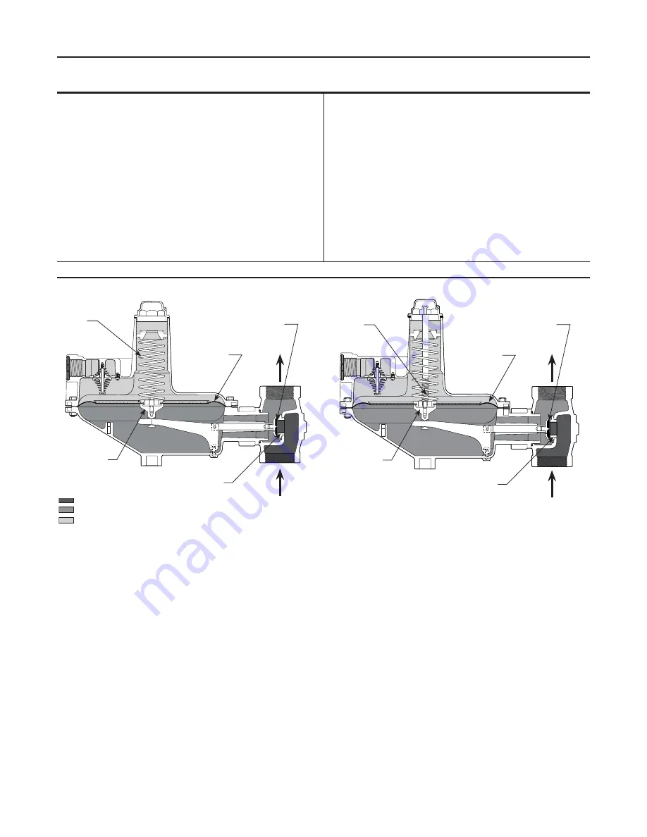
Refer to Figure 2. When downstream demand
decreases, the pressure under the diaphragm
increases. This pressure overcomes the regulator
setting (which is set by the control spring). Through
the action of the pusher post assembly, lever, and
valve stem, the valve disk moves closer to the orifice
and reduces gas flow. If demand downstream
increases, pressure under the diaphragm decreases.
Spring force pushes the pusher post assembly
downward, and the valve disk moves away from the
orifice, and the gas flow increases.
The Types S202 and S202H regulators include an
internal relief valve. Internal relief is used to help
minimize overpressure. Any outlet pressure above
the start-to-discharge point of the non-adjustable relief
spring moves the diaphragm off of the relief seat,
allowing excess pressure to discharge through the vent.
Typical start-to-discharge values are 7-inches w.c. to
2 psi (17 to 138 mbar) above the outlet pressure
setting, depending on control spring used.
Available Configurations
See Figure 3
Body Size and End Connection Styles
1-1/2 or 2 NPT inlet and outlet and
NPS 2 (DN 50) CL125 FF flanged
Maximum Allowable Inlet Pressures
(1)
See Table 1
Maximum Emergency Outlet Pressure
(1)
15 psig (1,0 bar)
Outlet Pressure Range
2.0-inches w.c. to 10 psig (5 mbar to 0,69 bar)
Orifice Size
1/4, 3/8, 1/2, 3/4, 1, and 1-3/16-inches
(6,4; 9,5; 13; 19; 25; and 30 mm)
Temperature Capabilities
-20° to 150°F (-29° to 66°C)
Pressure Registration
Internal
Approximate Weight
22 pounds (10 kg)
1. The pressure/temperature limits in this Instruction Manual and any applicable standard or code limitation for valve should not be exceeded.
INLET PRESSURE
OUTLET PRESSURE
ATMOSPHERIC PRESSURE
A6198
Type S202
Figure 2. Operational Schematics
A6197
A6198
INLET PRESSURE
OUTLET PRESSURE
ATMOSPhERIC PRESSURE
CONTROL
SPRING
RELIEF vALvE
SPRING
PUShER POST
PUShER POST
DIAPhRAGM
DIAPhRAGM
vALvE DISk
vALvE DISk
ORIFICE
ORIFICE
TyPE S201
TyPE S202


