Emerson CROSBY STYLE HC ISOFLEX Installation, Maintenance And Adjustment Instructions Download Page 9

9

⅝-11

60 (81)

90 (122)

120 (163)

¾-10

100 (136)

150 (203)

200 (271)

⅞-9

160 (217)

240 (325)

320 (434)

1-8

240 (325)

370 (502)

500 (6-78)

1⅛-8

350 (475)

525 (712)

700 (949)

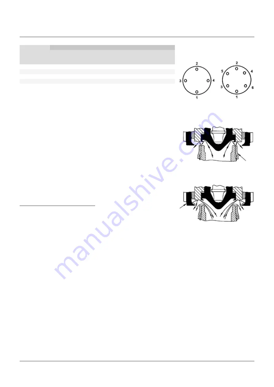
FIGURE 7 - EFFECT OF NOZZLE RING

FIGURE 8 - EFFECT OF GUIDE RING

7 OPERATION

Crosby Style HC/HCA safety valves open with a 
sharp pop at the set pressure and remain open, 
relieving rated capacity at 3% overpressure. 
As inlet pressure decays below the opening 
pressure, the safety valve remains open until 
a pressure about 4% below the set pressure 
is reached. At that point, the safety valve 
closes sharply.

Nozzle ring

Guide ring

CROSBY

®

 STYLES HC AND HCA ISOFLEX™ SAFETY VALVES

INSTALLATION, MAINTENANCE AND ADJUSTMENT INSTRUCTIONS

FIGURE 6 - TIGHTENING OF BONNET AND/OR 
COOLING SPOOL STUD NUTS

Stud thread

Torque (ft·lb) (Nm) to produce stress in stud bolts

30.000 psi (2.068 bar)

45.000 psi (3.203 bar)

60.000 psi (4.137 bar)

Stress

Stress

Stress

ft·lb (Nm)

ft·lb (Nm)

ft·lb (Nm)

4 studs

6 studs

NOTES

1.  Valve studs and nuts shall be clean and inspected 

visually to ensure freedom from any objectionable 
foreign matter, rust, burns or physical damage.

2.  With the bonnet in place, lubricate the bonnet 

studs threads, the nut threads and nut face with 
'Never-Seez' compound (which conforms to 
Government specification MIL-A-907B, Federal 
stock number 803-286-5453) or equivalent.

3.  Install nuts on the studs finger-tight.
4.  Tighten the nuts in the sequence shown in Figure 

6 to approximately one-half the torque value 
shown in the table. Repeat the same sequence 
of tightening to the torque value shown. Then, 
starting with the number 1 nut, tighten each nut in 
order in a clockwise or counterclockwise direction 
to the value shown in the table above.

5.  Wipe off excess lubricant.

Complete the valve assembly with the cap assembly as described in Section 10 - paragraph 'Assembly of cap' 
and seal wire the cap set screws.

The sharp opening is produced in two stages. 
The initial lift is produced when the steam 
pressure under the disc insert (5) exceeds 
the spring pressure. To aid in starting the 
popping action, steam escapes between the 
safety valve seats and is deflected by an angle 
on the nozzle ring (3) as shown in Figure 7. 
This escaping steam acts on the face of the disc 
holder (6) causing an unbalance and the safety 
valve pops open. As the disc holder moves 
vertically, steam begins to react against the 
guide ring (10) and to push the disc holder up 
to a high lift as shown in Figure 8. The reaction 
of the deflected steam pushes against the 
underside of the disc holder and lifts it still 
higher on an accumulation of pressure.
As the boiler pressure drops, the safety valve 
disc insert (5) settles to a moderate lift and 
closes sharply.
The nozzle ring (3) is primarily for ensuring 
sharp opening action. Raising the nozzle 
ring, bringing it closer to the face of the disc 
holder (6), eliminates 'simmer' or 'warn'.
The guide ring (10) is primarily for controlling 
blowdown. Raising the guide ring reduces the 
reactive pressures against the disc holder and 
reduces blowdown. Lowering the guide ring 
increases the reactive pressures against the 
disc holder and increases the blowdown.

Summary of Contents for CROSBY STYLE HC ISOFLEX

Page 1: ...ief product Precautionary statements in the form of warnings cautions and notes are used throughout this instruction to emphasize important and critical factors where applicable Examples WARNING An operating procedure or practice which if not observed strictly may result in injury to personnel or loss of life CAUTION An operating procedure or practice which if not observed strictly may result in d...

Page 2: ...nnet stud nut 16 Spring 3 17 Bottom spring washer 3 18A Top spring washer 3 18B Bearing pin 3 18C Locking pin 3 19 Bearing adapter 20 Bearing 21A Adjusting bolt 21B Adjusting bolt bearing 22 Adjusting bolt nut 23 Spindle nut 24 Spindle nut cotter 1 25 Cap 26 Cap set screw 27 Lever 28 Lever pin 29 Lever pin cotter 1 30 Forked lever 31 Forked lever pin 32 Forked lever pin cotter 1 34 Test clamp 36 T...

Page 3: ...installation and maintenance procedures specified in this manual will provide the utmost in safety a minimum of maintenance and a long service life Style HC is a high capacity reaction type safety valve designed for saturated and superheated steam applications to temperatures of 750 F Crosby Style HCA is a high temperature version of the Style HC with an alloy steel construction suitable to temper...

Page 4: ... 1 page 5 CROSBY STYLES HC AND HCA ISOFLEX SAFETY VALVES INSTALLATION MAINTENANCE AND ADJUSTMENT INSTRUCTIONS Ordering spare parts When ordering spare parts the valve size style and shop number and or serial number should be given together with set pressure part name and reference number The valve assembly number is shown on the valve nameplate as Shop number Spare parts may be ordered from any Em...

Page 5: ...s are directed or piped to a safe disposal area Welding of welded inlet valve body to boiler Welded inlet safety valve bodies should be welded to the boiler in accordance with applicable Code requirements The protective cover Figure 3 should be left in place until ready for the hydrostatic test of the unit If visual inspection is necessary the protective cover may be removed but should be replaced...

Page 6: ...tion 4 paragraph Factory preparation of welded inlet valves for shipment and Figure 3 Hydrostatic tests of these valves shall be conducted using hydrostatic test plugs as detailed in paragraph below Hydrostatic testing using hydrostatic test plugs Flanged inlet safety valves Flanged inlet safety valves should not be installed for hydrostatic testing Blank flanges should be used instead of gagging ...

Page 7: ...alues foot pounds obtained should be increased by a factor of approximately 25 to account for normal variations in friction safety valves and test conditions CAUTION Gags should not be used when inlet pressures are more than 10 greater than the safety valve set pressure Damage to the valve may result CAUTION Should any safety valve show seat leakage the pressure must be lowered until the leakage s...

Page 8: ...king device see Figure 14 Refer to instruction I 1167 for detailed instructions in the use of this device After the spacer blocks have been removed set the nozzle ring 3 and guide ring 10 according to Section 10 paragraph Setting of rings Lock the nozzle ring set screw 4 and the guide ring set screw 11 in place making sure that the proper set screws are installed and engaged fully in a notch Lock ...

Page 9: ...e table Repeat the same sequence of tightening to the torque value shown Then starting with the number 1 nut tighten each nut in order in a clockwise or counterclockwise direction to the value shown in the table above 5 Wipe off excess lubricant Complete the valve assembly with the cap assembly as described in Section 10 paragraph Assembly of cap and seal wire the cap set screws The sharp opening ...

Page 10: ... and the hydraulic set pressure device Refer to test procedure T 1652 for detailed instructions in the use of the air set pressure device and instruction I 11288 for detailed instructions in the use of the hydraulic set pressure device System pressure The second method of set pressure testing is by raising the system pressure and popping the safety valve Set pressure testing using this method will...

Page 11: ...reached or if it does not pop at the nameplate set pressure the following steps for set pressure adjustment should be taken WARNING Set pressure adjustment should not be made until the system pressure is 10 to 20 below the actual popping pressure of the safety valve The adjusting bolt should never be turned when the vessel pressure is near the set pressure of the safety valve Remove the lever 27 f...

Page 12: ...s are custom fitted to each safety valve and should never be interchanged The spring washers are fitted to each end of the spring The spring and washers must be kept intact as a unit Before disassembly spare parts and service equipment such as lapping compound lapping blocks and jacking gear should be available Disassembly Disassembly retaining spring compression If the safety valve is to be recon...

Page 13: ...he guide Remove the spindle 12 from the disc insert 5 by lifting the spindle slightly to engage the threads and unscrewing the spindle from the disc insert Unscrew the nozzle ring 3 from the nozzle 1B CROSBY STYLES HC AND HCA ISOFLEX SAFETY VALVES INSTALLATION MAINTENANCE AND ADJUSTMENT INSTRUCTIONS Disassembly without retaining spring compression To disassemble the safety valve completely and not...

Page 14: ... with this compound lap again with fine compound using a new lapping block surface The first step can be omitted unless much lapping is called for Next lap again using a polish compound CAUTION Never lap the disc insert against the nozzle CROSBY STYLES HC AND HCA ISOFLEX SAFETY VALVES INSTALLATION MAINTENANCE AND ADJUSTMENT INSTRUCTIONS Repair procedure Lapping or refurbishing of valve seats Good ...

Page 15: ...nsert seats When the damage to the disc insert 5 seat is too severe to be removed by lapping the disc insert should be replaced Disc inserts should never be remachined Remachining the insert will change critical dimensions affecting the operation of the safety valve The disc insert seating surface may be lapped if the minimum seat height shown in Figure 10 is maintained Refurbishment of nozzle sea...

Page 16: ... Never Seez is manufactured by Bostik Corporation 2 Molykote is manufactured by Dow Corning Corporation Stand assembly on a clean surface making certain that the end of the spindle rotates freely on the disc insert bearing surface not loading on the insert threads Thread the disc holder retainer down until it makes contact with the disc holder Locate the hole in the spindle relative to a notch on ...

Page 17: ...pindle threads with a light coat of Never Seez Molykote G or equivalent Thread the appropriate spindle adapter 6 on the spindle until it comes in contact with the jacking device piston Attach the hand operated hydraulic pump 7 and hose 8 To raise the valve spindle pressure is applied to the jacking device assembly with the hand operated hydraulic pump This activates the piston 2 which will rise co...

Page 18: ...htened Assembly of cap see Figure 1 The assembly of the cap is referred to several times in this instruction The cap assembly consists of the spindle nut 23 cap 25 forked lever assembly forked lever 30 forked lever pin 31 and forked lever pin cotter 32 and the lever assembly lever 27 lever pin 28 and lever pin cotter 29 11 SPARE PARTS Emerson recommends spare parts as shown on the parts list with ...

Page 19: ...VICE REQUIREMENTS Field service Crosby operates an extensive field service organization capable of adjusting setting and maintaining Crosby valves worldwide Emerson service technicians factory trained and long experienced in servicing safety valves are located throughout the world for fast response to our customers needs It is strongly recommended that on new installations a Emerson service techni...

Reviews: