


11
CROSBY
®
STYLES HC AND HCA ISOFLEX™ SAFETY VALVES
INSTALLATION, MAINTENANCE AND ADJUSTMENT INSTRUCTIONS
• Nozzle ring and guide ring adjustment
The guide ring (10) is the principal blowdown
control ring in the safety valve. To change the
guide ring position, remove the guide ring
set screw (11) from the body (1A). Insert a
screwdriver or similar tool and engage one
of the notches (these can be seen through
the set screw hole).
The guide ring can then be turned to the
right or left as desired. Moving the guide
ring to the right (counterclockwise) raises
it and decreases the blowdown. The guide
ring should never be moved more than
ten notches either way without retesting
the valve.
After each adjustment, always replace,
tighten and lock wire the set screw, being
careful that its point engages a notch.
The nozzle ring (3) is necessary for obtaining
the pop action of the safety valve. This
ring setting is determined at the factory
and rarely needs further adjustment.
Turning the ring to the right
(counterclockwise) raises it and results in a
strong pop action. Blowdown will increase.
Turning the ring to the left (clockwise) lowers
the ring, decreases the blowdown and may
result in warn or simmer if lowered too far.
The range of adjustment of the nozzle ring is
limited and it should not be moved more than
one notch at a time.
The valve performance should be checked
after each adjustment. After each adjustment,
always replace, tighten and lock wire the set
screw, being careful that its point engages
a notch.
Whenever ring adjustments are changed,
a record should be kept of the number of
notches and the direction in which the ring
was moved. This will make it possible to
return to the original setting in case of error.
After the safety valve has been adjusted to
close at the desired pressure, remove the
lifting gear and make sure the adjusting bolt
nut (22) and the set screws (4 and 11) are
installed properly and tightened.
If different ring locations are obtained
after testing, restamp the top of the valve
bonnet (13) with the new (tested) ring settings.
Install the cap assembly (25) according to
Section 10 - paragraph 'Assembly of cap',
making sure there is
1
/
16
” clearance between
the spindle nut (23) and forked lever (30).
Seal wire the cap screws (26) and set
screws (4 and 11).
• Set pressure adjustment
If the safety valve pops before the nameplate
set pressure is reached, or if it does not pop
at the nameplate set pressure, the following
steps for set pressure adjustment should
be taken:
WARNING
Set pressure adjustment should not be made until
the system pressure is 10% to 20% below the
actual popping pressure of the safety valve. The
adjusting bolt should never be turned when the
vessel pressure is near the set pressure of the
safety valve.
- Remove the lever (27), forked lever (30)
and cap (25).
- Loosen the adjusting bolt nut (22).
- If the safety valve has popped below the set
pressure stamped on the valve nameplate,
an increase in set pressure is necessary.
This is obtained by turning the adjusting
bolt (21) clockwise (compressing the
spring). If the safety valve popped above
the nameplate set pressure, decrease
the set pressure by turning the adjusting
bolt counterclockwise (relieving spring
compression).
- After each adjustment, the adjusting bolt
nut (22) should be tightened securely to
prevent loosening of the bolt. The lifting
gear should be reinstalled.
- After the safety valve has been adjusted to
open at the desired pressures, remove the
lifting gear and make sure the adjusting bolt
nut (22) is installed properly and tightened.
Install the cap assembly (25) according to
Section 10 - paragraph 'Assembly of cap',
making sure there is approximately
1
/
16
”
clearance between the spindle nut (23)
and the forked lever (30). Seal wire the cap
screws (26) and set screws (4 and 11).
WARNING
Never make ring adjustments with the vessel
under pressure without gagging the safety valve
properly. Be careful to use only enough torque to
hold the valve closed. Over-gagging may damage
the valve internals.
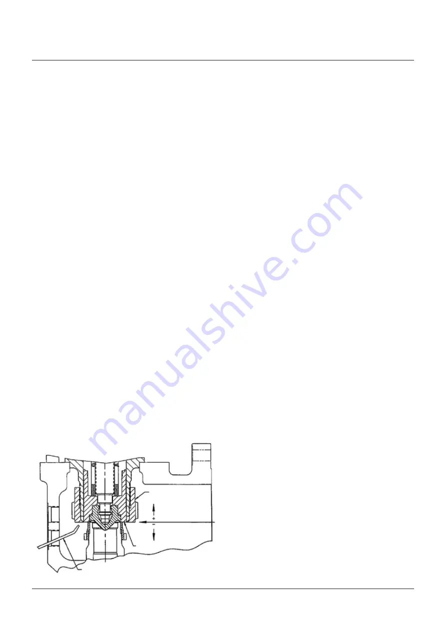
FIGURE 9 - RING SETTINGS AND ADJUSTMENTS
Steel rod to check
guide ring position
* Factory setting of guide ring
position (+/-) notches from
level stamped on bonnet
Disc holder
Guide ring
Level position*
The nozzle ring and guide ring settings are
determined at the factory. Their locations are
stamped on the valve bonnet (13) where the
cap is seated. Adjusting (guide) ring positions
are recorded as plus (+) or minus (-) numbers
from the level position. An illustration of the
guide ring sign convention is presented in
Figure 9. However, if the desired blowdown was
not obtained, it will be necessary to adjust the
rings. The following steps should be taken:
However, in case the guide ring (10) does not
give the desired operating characteristics
under all conditions of operation, the nozzle
ring may be adjusted to control the valve
operation for very fine adjustment. The nozzle
ring is adjusted by removing the nozzle ring
set screw (4) from the valve body (1A).


