


16
K
.008 - .012
4 - 6
K
2
.010 - .012
5 - 6
M/M
2
.010 - .012
5 - 6
10 VALVE ASSEMBLY
General information
Apply a light coat of 'Never-Seez
®
'
[1]
lubricant
on the new nozzle ring (3) threads. Screw the
nozzle ring on the nozzle leaving the top of the
ring slightly above the seating plane. This will
help protect the seating surface of the nozzle
during the assembly process.
Spot lap the disc insert (5) to the spindle (12)
and clean thoroughly. Apply a thin coat of
'Molykote
®
321R'
[2]
, or equivalent, dry film
lubricant to the bearing surface of the disc
insert and spindle tip.
Apply a light coat of 'Never-Seez
®
' to the
threads of the spindle (12), disc insert (5) and
disc holder retainer (7). Thread the disc holder
retainer on the spindle and slide the disc
holder (6) over the lower end of the spindle.
Thread the disc insert onto the spindle and set
the retainer clearance (see Figure 13).
Spot lap the guide (9) with the mating surface
on the body (1A) and clean the surface
thoroughly. Then place the guide into position
on the body.
With the disc holder (6), disc insert (5), disc
holder retainer (7) and spindle (12) assembled,
place the assembly into position in the body
and guide.
Place the spring and washer assembly into
position on the bonnet/cooling spool assembly.
Note that the anti-rotation pins of the top spring
washer should be straddling the bonnet.
The valve can be assembled further using
either of the following two methods.
• Valve assembly without using the hydraulic
jacking device
Utilizing a suitable lifting device, place the
bonnet/spring assembly over the spindle (12)
and into position on the body (1A). Note that
the adjusting bolt (21A) will be in the retracted
position thereby allowing the bonnet (13) to be
seated on the body.
With the assembly in place, turn the nozzle
ring (3) clockwise (with a screwdriver through
the set screw hole) until the top surface is
below the seating plane. The bonnet stud
nuts (15) may now be torqued in place.
NOTES
1. Never-Seez is manufactured by Bostik
Corporation.
2. Molykote is manufactured by Dow Corning
Corporation.
Stand assembly on a clean surface making
certain that the end of the spindle rotates freely
on the disc insert bearing surface (not loading
on the insert threads). Thread the disc holder
retainer down until it makes contact with the
disc holder.
Locate the hole in the spindle relative to a notch
on the retainer. Back off the retainer by turning
it counterclockwise to establish the proper
clearance.
The clearances, and the corresponding number
of notches, are listed in the table. With the
proper clearance established, install the
retainer cotter pin through the appropriate
notch and spindle.
CAUTION
The cotter pin head should be turned so that it fits
between and into the retainer notch and makes
contact with the spindle. The split ends of the
cotter pin should both be bent downward.
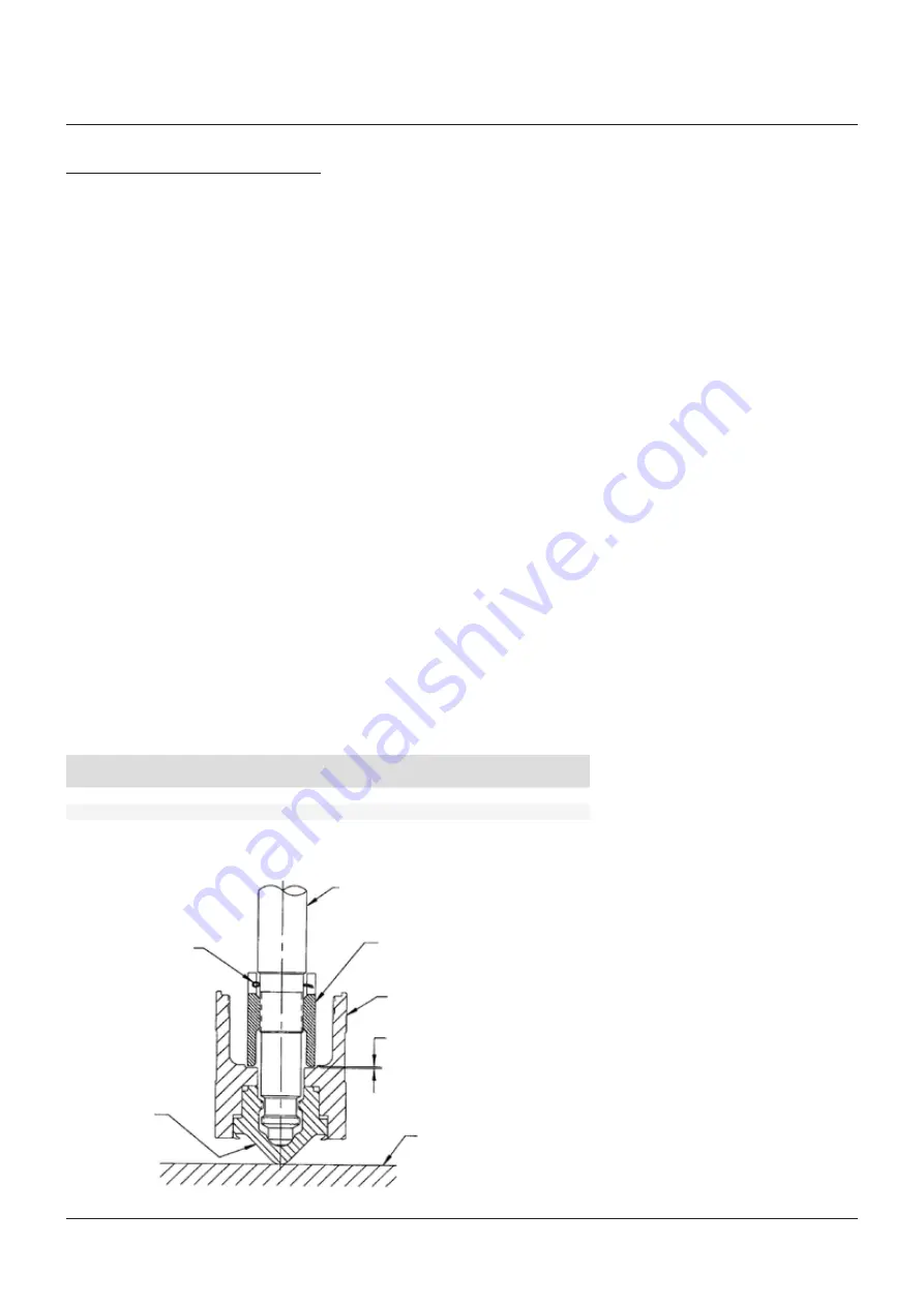
FIGURE 13 - RETAINER NUT CLEARANCE
Spindle
Disc holder retainer
Disc holder
Retainer clearance
Clean surface
Cotter pin
Disc insert
Note that a criss-cross torquing pattern
should be utilized to ensure even
compression as illustrated in Figure 6.
Once the bonnet stud nuts (15) are in place,
the adjusting bolt (21A) may be turned,
thereby compressing the valve spring (16).
Tighten the adjusting bolt until the distance
is the same as that recorded when the valve
was disassembled (see page 11). At this point,
the adjusting bolt nut (22) shall be tightened
in place.
Valve orifice size
Retainer clearance
(inches)
Corresponding number
of retainer notches
CROSBY
®
STYLES HC AND HCA ISOFLEX™ SAFETY VALVES
INSTALLATION, MAINTENANCE AND ADJUSTMENT INSTRUCTIONS
One method may be preferred over the
other depending on the valve size and/or set
pressure.
Assembly of the valve superstructure
and the compression of the spring may
be accomplished by two different method
as follows:
NOTE
The setting of the spring compression by this method
is only a very rough estimate of the valve set pressure.
The valve will require set pressure testing prior to
returning to service (refer to Section 8 - paragraph
'Set pressure testing and valve adjustment').


