November 2021
Installation, Operation and Maintenance Manual
DOC.IOM.RG.US Rev. 11
32
Section 15: Drawings and Schematics
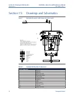
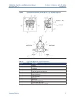
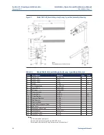
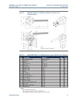
Drawings and Schematics
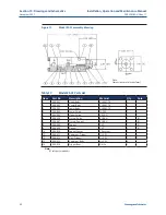
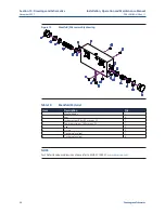
Figure 13
Model ES-01 assembly drawing
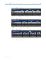
Table 17.
Model ES-01 Parts List
Item
Part No.
Description
Material
Qty.
Note
1
906-001
Upper Body
AL 6061-T6
1
2
906-002
Center Body
AL 6061-T6
1
3
906-003
Lower Body
AL 6061-T6
1
4
906-004
Lower Spring
SS 302
1
5
906-005
Upper Spring
CR VAN
1
6
906-006
O-ring - Body
BUNA N
2
(Y)
7
906-007
O-ring - Poppet
BUNA N
1
(Y)
8
906-008
Poppet
PVC
1
(Y)
9
906-009
Plunger
PVC
1
(Y)
10
906-010
Poppet Spacer
Alloy steel
1
11
906-011
Capscrew - Trigger
Gr. 5 PL
1
12
906-012
Nut - Trigger
Gr. 5 PL
1
13
906-013
Capscrew - Body
Gr. 5 PL
4
14
906-014
Trigger Boot
Nitrile
1
Note:
-
(Y) soft parts repair kit
IN
OUT
Note:
Dimensions are in inches [mm]
EXH

