Installation, Operation and Maintenance Manual
DOC.IOM.RG.US Rev. 11
November 2021
33
Section 15: Drawings and Schematics
Drawings and Schematics
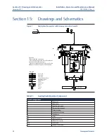
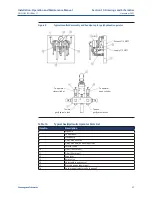
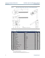
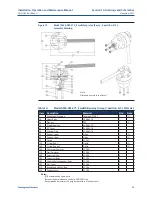
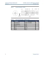
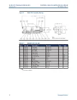
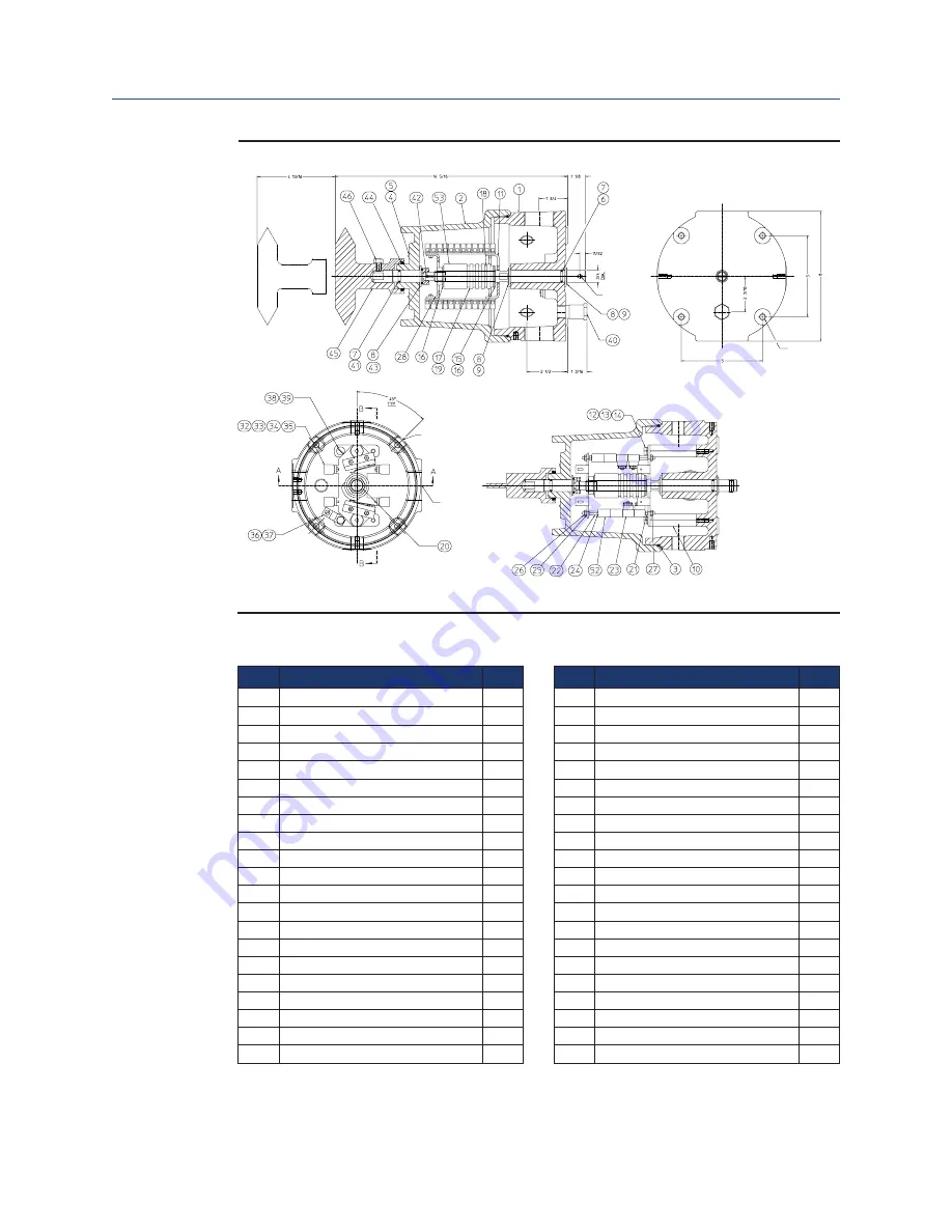
Figure 14
Limit switch SW44 assembly drawing
Section A-A
Access
clearance
1/4 Drill thru
max
Bottom view
3/8-16 Tap 1" Deep
4-Holes
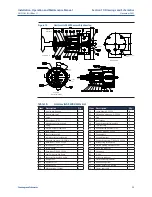
Table 18.
Limit switch SW44 Parts List
Item Description
Qty.
1
Limit switch housing
1
2
Limit switch cover
1
3
O-ring
1
5
Drive screw 1/4" SS
4
6
Actuator shaft - limit switch
1
7
O-ring
2
8
Washer, nylon for cam shaft
3
9
Snap ring SS
2
10
Post for limit switch
2
11
Lower bracket for limit switch
1
12
Hex head cap screw,1/4-20x3/4, SS 304
2
13
Flatwasher, 1/4 SAE, SS 304
2
14
Lockwasher, 1/4, SS 304
2
15
Spring washer
1
16
Flatwasher, 5/8 SAE, SS 304
3
17
Cam for limit switch, delrin
4
18
Spacer for limit switch, delrin
5
20
Hex jam nut
1
21
Hex spacer .125
4
22
Hex spacer .50
4
23
Micro switch w/ 3' leads
4
1/2 NPT
6 Places
1 1/2 NPT
2 Places
Top view
(cover removed)
Item Description
Qty.
24
Lockwasher, #6, SS 304
20
25
Flatwasher, #6 large o.D., SS 304
16
26
Stud
4
27
Hex locknut
8
28
Upper bracket for limit switch
1
32
Terminal strip
4
33
Round slotted machine screw
8
34
Hex nut, 4-40 unc, SS 304
4
35
Tag numbers
2
36
Ground terminal
1
37
Hex head cap screw,1/4-20x1/2, SS 304
1
38
Washer, ring terminal cup
1
39
Slotted binding machine screw
1
41
Shaft, top indicator
1
42
Spring pin
1
43
O-ring
1
44
Wiper, tip indicator
1
45
Limit switch top indicator
1
46
Hex head cap screw
1
52
Spacer, limit switch stackup
8
53
Spacer, cam shaft
1

