1
2
2
3
2
6
5
7
7
8
7
7
7
8
8
7
4
2
6
5
7
8
November 2021
Installation, Operation and Maintenance Manual
DOC.IOM.RG.US Rev. 11
34
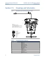
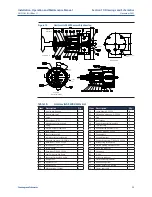
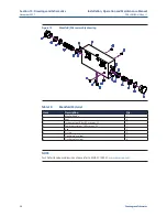
Section 15: Drawings and Schematics
Drawings and Schematics
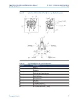
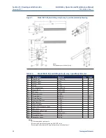
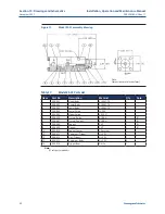
Figure 15
Manifold/filter assembly drawing
Table 19.
Manifold Parts List
Item
Description
Qty.
1
Manifold body
1
2
Seal
4
3
Instrument gas filter, 25 microns, SS
1
4
Power gas strainer, 140 microns, SS
1
5
Cap
2
6
O-ring
2
7
Flush plug level seal
7
8
Flush plug level seal
4
NOTE:
For Shafer Handpump drawings, please refer to MHP-01102001:

