background image


Installation, Operation and Maintenance Manual

IO-70100   Rev 3   7-15


The Emerson Network Power 570/560 Series 
Surge Protective Devices (SPDs) are high 
quality, high energy surge current diversion 
systems designed to protect sensitive 
equipment from damaging transient voltage 
surges. Proper installation is required for 
maximum system performance. 
The installer should perform the following 
steps to assure a quality installation. The 
entire installation manual should be read 
before starting installation. These 
instructions do not replace national or local 
electrical codes. Check applicable electrical 
codes to ensure compliance. Installation of the 
SPD system should only be performed by 
qualified personnel. 
1. Insure that all power is removed before 
beginning installation. A qualified licensed 
electrician shall install all electrical 
connections. 
2. The standard SPD is provided in a NEMA 4 or 
NEMA 4X rated enclosures suitable for use in 
indoor or outdoor installations. 
3. Determine where the SPD is to be 
mounted, allowing for minimum length of 
wire between itself and the input power 
terminals of the service panel. Punch or cut 
the proper hole size  in  the  side  of  the  SPD  
closest  to  the  knockout  to  be utilized in the 
service panel. Drill mounting holes in wall at 
location picked for SPD next to service panel 
using mounting dimensions shown in the 
table below. Mount surge suppressor to wall 
using 3/8” mounting hardware.


4. Connect black wires (line or phase) marked 
L1/A, L2/B or L3/C, the white wire (neutral) 
marked N, and the green wire (ground) 
marked G, of the SPD using the wire range 
listed below. To yield the best performance of 
the SPD within the electrical distribution 
system, keep all conductors as short as 
possible and avoid sharp bends.


5. Connection to the unit’s summary alarm 
contacts shall be with #18 – 22 AWG. The 
ratings of the Form ‘C’ contacts are 5 amps 
at 250 VAC maximum with a power factor of 
1.0. For additional information, see 
“Monitoring” section.


6. Apply power. The surge protector is fully 
operational when the GREEN LED’s on the 
modules and the front door of enclosure are 
illuminated. If the GREEN LED’s are  

 
extinguished or a RED LED  is  illuminated, 
check to ensure that power is applied to the 
SPD. If an abnormal indication is present, 
remove power to the SPD and contact 
Emerson Network Power Surge Protection at 

1-800-288-6169 or 1-607-721-8840.


7. Periodically monitor the status of the 
LED’s. Reduced protection exists if the GREEN 
LED’s are extinguished or the RED LED is 
illuminated. Please contact Emerson Network   
Power   Surge   Protection   at :   

1-800-288-6169   or


1-607-721-8840.


8. The protection modules in these SPD’s 
may be replaceable, contact Emerson 
Network Power Surge Protection for 
replacement.


NOTICE - If the SPD model is configured to 

include a neutral connection (“Y”, “H”, 

“S”, “N”), and a Neutral connection is not 

available, please contact factory.


(With AC Applied) 
Pin 1 = Normally Open 
Pin 2 = Common 
Pin 3 = Normally Closed

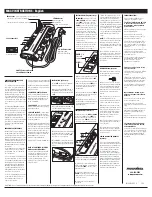
INSTALLATION INSTRUCTIONS

7

Courtesy of NationalSwitchgear.com

Summary of Contents for 500 Series

Page 1: ...500 Series 570 560 Surge Protective Device Installation Operation and Maintenance Manual Courtesy of NationalSwitchgear com ...

Page 2: ...ons 5 Voltage Protection Rating 5 Circuit Ampacity Limitations 5 System Grounding and Bonding 5 Grounding Electrode 6 Neutral Connection 6 Parallel Connection Wire Diagram 6 INSTALLATION INSTRUCTIONS Product Installation 7 Suggested Circuit Breaker and Wire Size Chart 8 Dimensional Information Chart 8 Suggested Circuit Breaker and Wire Size Motorola R56 Approved Models 9 Dimensional Information Mo...

Page 3: ... solid state motor drives etc For interconnected electronicloads suchasby wayofdatacabling transientsurge suppression should also be applied to the interconnecting wiring data cables Environment Unit is designed for operation indoors in ambient temperatures of 40ºC 40ºF to 60ºC 140ºF with a relative humidity of 0 to 95 non condensing The unit is provided in an industrial use enclosure which is dus...

Page 4: ...uvent être utilisés pour mettre en garde contre des pratiques dangereuses qui peuvent entraîner des dommages matériels seulement Units that include the ACTIVE SURGE MONITOR option 3 1 2 3 4 5 6 7 8 9 10 11 12 13 MODEL NUMBER CONFIGURATION Model _ _ _ _ _ _ _ _ _ _ _ _ _ 11 Enclosure N Caseless open style G Type 4 metal H Type 4X Stainless Steel J Type 4X Plastic F Type 12 Flushmount metal 12 UL 14...

Page 5: ...Installation Operation and Maintenance Manual IO 70100 Rev 3 7 15 CONFIGURATION VOLTAGE CHART 4 Courtesy of NationalSwitchgear com ...

Page 6: ...ational Electric Code 2008 Edition NEC 285 21 Connections NEC 285 23 Type 1 SPD s Shall be installed in accordance with 285 35 A and B A Installation Type 1 SPD s shall be installed as follows 1 Type 1 SPD s shall be permitted to be connected to the supply side of the service disconnect as permitted in 230 82 4 or 2 Type 1 SPD s shall be permitted to be connected in Type 2 locations as specified i...

Page 7: ... power conductors in the same raceway conduit When metallic raceways are used adequate electrical continuity must be maintained at all raceway connections particularly raceway terminations to the electrical enclosures The use of isolating bushings or other means to interrupt a metallic conduit run is a potential safety hazard and is not recommended Grounding Electrode Surge protective devices do n...

Page 8: ...sing 3 8 mounting hardware 4 Connect black wires line or phase marked L1 A L2 B or L3 C the white wire neutral marked N and the green wire ground marked G of the SPD using the wire range listed below To yield the best performance of the SPD within the electrical distribution system keep all conductors as short as possible and avoid sharp bends 5 Connection to the unit s summary alarm contacts shal...

Page 9: ... Compression Lug N 16 406 12 305 17 25 438 9 5 241 35 lb 15 9 kg Rotary Disconnect R 16 406 16 406 17 25 438 10 254 45 lb 20 4 kg 160kA 250kA Compression Lug N Rotary Disconnect R 20 508 16 406 21 25 540 10 254 55 lb 24 9 kg 300kA 375kA Compression Lug N Rotary Disconnect R 20 508 20 508 21 25 540 14 356 85 lb 38 6 kg 500kA Compression Lug N Rotary Disconnect R 20 508 24 610 21 25 540 18 457 95 lb...

Page 10: ...ble Range 15A 175A Suggested Size 80A Connection Wire Allowable Range 14 2 O Suggested Size 4 Motorola R56 Approved Models Model Number R56 Type Weight 570SA16FNRJ1S Type 1 MOV SAD Hybrid 28 lb 12 7 kg 570YA16FNRJ1S Type 1 MOV SAD Hybrid 32 lb 14 5 kg 560SA16FNRJ1S Type 2 MOV Only 24 lb 10 9 kg 560YA16FNRJ1S Type 2 MOV Only 28 lb 12 7 kg 9 Courtesy of NationalSwitchgear com ...

Page 11: ...0 This status does not indicate that the unit is in need of repair Active Surge Monitor Optional A web based monitoring device allowing real time power quality measurements logged events statistical summaries and premium power protection Understanding the severity type and timing of the event allows you to analyze trends and ultimately better manage your electrical system See IO 70109 for further ...

Page 12: ...varyfromsitetosite Inspectionsforfailedsurgemodulesusingavailable diagnosticsshouldbedoneroutinely weeklyor monthly Emerson Network Power Surge Protection 100 Emerson Parkway Binghamton NY 13905 800 288 6169 Phone U S Canada Only 607 721 8840 Outside U S 607 722 8713 FAX United States of America Emerson Network Power European Headquarters Via Leonardo Da Vinci 8 Zona Industriale Tognana 35028 Piov...

Reviews: