


EMC
®
VNX
™
Procedure Generator
EMC CONFIDENTIAL
version: 4.5
38 of 51
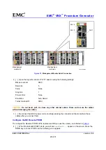
AC
AC
AC
AC
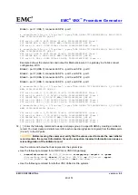
CPU power LED
CPU fault LED
CPU unsafe to
remove LED
CNS-001668
Power supply/cooling
(fan) LED
Blade enclosure
fault LED
Blade enclosure
power LED
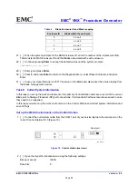
Figure 20
BE, power/cooling module, and CPU module fault LEDs (bezel removed)
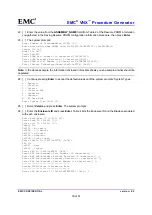
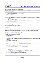
11. [ ] Query the system to display the new WWNs assigned to each Blade in the enclosure by typing the
following command.
IMPORTANT:
Ensure that you capture the output returned for the following commands. The new
initiator records cannot be created without this information.
#
/nasmcd/sbin/t2tty -c <slot_number> "fcp topology”
Example Output for BE 0:
# /nasmcd/sbin/t2tty -c 2 "fcp topology"Output:
FCP HBA 0: FC-AL ALPA 000001 Node 50060160c4602075 Port 5006016044602075
FCP HBA 1: FC-AL ALPA 000001 Node 50060160c4602075 Port 5006016144602075#
/nasmcd/sbin/t2tty -c 3 "fcp topology"Output:
FCP HBA 0: FC-AL ALPA 000001 Node 50060160c4602075 Port 5006016044602075
FCP HBA 1: FC-AL ALPA 000001 Node 50060160c4602075 Port 5006016144602075
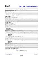
12. [ ] Construct the new Blade port WWNs (HBA UIDs) and record these values in Table 6.
Construct each WWN by grouping the unformatted Node and Port values of each Blade port into a
single string delimited with colons between every two digits.
For example, using the values shown for Blade 2 in the output shown in the previous step, the WWNs
for Blade 2 are:
Blade 2 - port 0: 50:06:01:60:c4:60:20:75:50:06:01:60:44:60:20:75
Blade 2 - port 1: 50:06:01:60:c4:60:20:75:50:06:01:61:44:60:20:75


