43
EN
IT
75ohm
12
0
PRI
12
0
PRI
L
P
P
L
L
P
L
P
P
L
J1
D
J1
D
J1
D
J1
D
J1
D
V V
V
V
4
3
1
4
R1
4
0
S1 15
R2
5
4
F2 3
PRI
CH S F1
D
C
B
A
PRI
+U
-
+I
V3
V2
V4
V1
V
-
+
V
4
8
V
6
V
4
8
6
2
1
3
3
5
4
1 2 3 4 5
5
4
3
2
1
4 5
3 3
1 2
5
V
3
4
1
R1
CH S F1 F2 3 4 5 +
15 O
4
R2
4
PRI
+I
-
S1
M1
V1
V2
M2
4 5
V 1 3
- +
75 Ohm
75 Ohm
+
-
3
1
V
5
4
M2 V2 V1 M1
S1
-
+I
PRI
4
R2
4
O
15
+
5
4
3
F2
F1
S
CH
R1
+L
M1
V2
+I
SR
V1
VL
F1
4
F2
CH
V
3
1
M
5
8
6
4
+L
M1
V2
+I
SR
V1
VL
F1
4
F2
CH
V
3
1
M
5
8
6
4
+L
M1
V2
+I
SR
V1
VL
F1
4
F2
CH
V
3
1
M
5
8
6
4
+L
M1
V2
+I
SR
V1
VL
F1
4
F2
CH
V
3
1
M
5
8
6
4
+L
M1
V2
+I
SR
V1
VL
F1
4
F2
CH
V
3
1
M
5
8
6
4
Distributore
Art. 5556/004
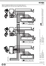
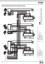
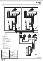
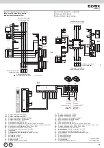
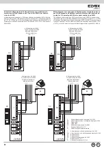
IMPIANTO CONDOMINIALE CON DUE O PIÙ TARGA PRINCIPALE VIDEO E DUE O PIÙ TARGHE A PIÈ SCALA VIDEO O AUDIO
INSTALLATION FOR BLOCK OF FLATS WITH TWO OR MORE MAIN VIDEO ENTRANCE PANELS OR MORE VIDEO OR AUDIO OUTDOOR EN-
TRANCE PANEL (BUILDING COMPLEX).
D- Unità elettronica video Art. 1285
DX-Targa serie 1200, 8000
P- Pulsante supplementare serratura
L- Serratura elettrica 12V~
Parametri da impostare:
Parametri da modificare sulle targhe
“a piè scala”.
- Par. 01 “Utent.Iniziale”
- Par. 02 “Utente Finale”
I numeri compresi tra utente ini-
ziale e utente finale di ogni targa
non devono coincidere con quelli di
un’altra targa “a piè scala”.
Parametri da modificare sulla targa
principale.
- Par. 24 “Durata suono”
Il tempo di chiamata della targa
principale dev’essere maggiore del
tempo di chiamata delle targhe “a
piè scala” (almeno di un secondo).
Rif. schema si040
Ref. diagram si040
Parameters to set:
Parameters to modify on the sec-
ondary entrance panels.
- Par. 1 “Initial User”
- Par. 2 “Final User”
The numbers between initial user
and final user of each entrance panel
must not be the same as those of an-
other secondary entrance panel.
Parameters to modify on the main
entrance panel.
- Par. 19 “Conv. Duration”
The call time of the main entrance
panel must be greater than the call
time of the secondary panels (by at
least one second).
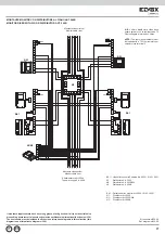
Per la disattivazione del generatore di corrente tagliare il ponticello metal-
lico “J1” posizionato sul retro (in basso a destra) dell’unità elettronica.
Disconnect the metal jumper located on the side of the terminal block.
Montante
Cable riser
Montante
Cable riser
Montante videocitofoni
Monitor cable riser
Montante videocitofoni
Monitor cable riser
Rete
Mains
Rete
Mains
Rete
Mains
Rete
Mains
Rete
Mains
Rete
Mains
F3
F1
F1
N2
Q3
Q3
Q1
Q1
T
T
F5
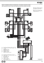
D0 - Video electronic unit with keypad and
display Art. 1286
DX - Entrance panel
F1 - Power supply Art. 6948
F3 - Addictional power supply Art. 6942
F5 - Addictional power supply Art. 6982
L - Electric lock 12V A.C.
N2 - Distributor Art. 5556/004
P - Additional push-button for lock
T - Transformer Art. M832
Q1 - Relay Art. 0170/001
Q3 - Relay Art. 0170/051
D - Unità elettronica video con tastiera e
display Art. 1286
DX - Targa video
F1 - Alimentatore Art. 6948
F3 - Alimentatore supplementare Art. 6942
F5 - Addictional power supply Art. 6982
L - Serratura elettrica 12V A.C.
N2 - Distributore Art. 5556/004
P - Pulsante supplementare serratura
T - Trasformatore Art. M832
Q1 - Relè Art. 0170/001
Q3 - Relè Art. 0170/051
DX
1
2
3
4
5
6
7
8
9
0
ABC
DEF
GHI
JKL
MNO
PQRS
TUV
WXYZ
.,;
R
CANC
DX
1
2
3
4
5
6
7
8
9
0
ABC
DEF
GHI
JKL
MNO
PQRS
TUV
WXYZ
.,;
R
CANC
DX
1
2
3
4
5
6
7
8
9
0
ABC
DEF
GHI
JKL
MNO
PQRS
TUV
WXYZ
.,;
R
CANC
DX
1
2
3
4
5
6
7
8
9
0
ABC
DEF
GHI
JKL
MNO
PQRS
TUV
WXYZ
.,;
R
CANC
DX
1
2
3
4
5
6
7
8
9
0
ABC
DEF
GHI
JKL
MNO
PQRS
TUV
WXYZ
.,;
R
CANC
D0
D0
D0
D0
D0

