26
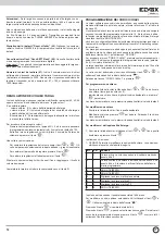
ENTRANCE PANEL VOLUME ADJUSTMENT
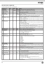
The entrance panel volume levels can be adjusted by modifying parameters
42, 43, 44 or via the “adjust volumes” menu when a call is in progress.
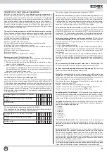
It is possible to adjust:
- external volume. This is the volume of the entrance panel loudspeaker.
- internal volume. This is the volume of the entrance panel microphone
signal and therefore of the system audio line.
- Balance. This is the balance of the loudspeaker / microphone signal, for
eliminating feedback caused by the Larsen effect.
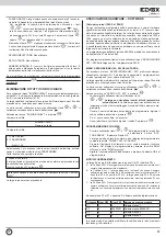
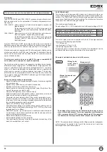
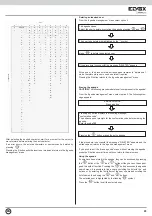
To access the volume adjustment menu:
6LPXOWDQHRXVO\SUHVVSXVKEXWWRQV5DQGHQWHUWKHWHFKQLFDOSUR
-
gramming password (parameter 8). The default value is 123.
$IWHUHQWHULQJWKHYROXPHDGMXVWPHQWPHQXHQWHUWKHQXPEHURIWKHLQ
-
ternal user to call and press the “
” button.
Once the call is in progress:
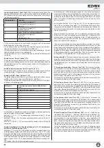
7RFKDQJHWKHYROXPHOHYHOXVHWKH
“
” and “
” buttons. The level
of the selected parameter is indicated by the bar graph displayed on-
screen;
7RFKDQJHWKHSDUDPHWHUSUHVVWKH
“
” button
7RVDYHWKHQHZVHWWLQJVSUHVVWKH
“
” button.
Repeat the last three steps until the desired volume level is reached.
When the volume adjustment is complete, end the conversation using the
R button.
PROGRAMMING KEYCODES
Software keys are codes which, depending on the programming operation,
release the door lock, activate function F1 or activate function F2.
The key is inserted by the user from the main menu according to the mode
programmed in parameter 10. If the key is active, the functions programmed
for that key are actuated, otherwise the entrance panel displays the mes-
sage “NOT FOUND”. The key can be configured using the key programming
submenu. The configuration parameters are initialised with default values
which are identical for all keys.
The key can be always active or it can be activated within a time band. The
key can also be deactivated without removing it from the list by means of bit
1 from the “OPTIONS” submenu
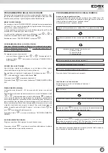
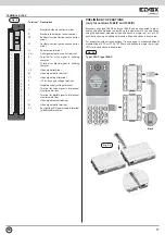
To access the “KEYCODES” menu, simultaneously press push-buttons R +
4 and enter the technical programming password (parameter 8). The default
value is 123.
The entrance panel initially displays the firmware version then after 10 se-
conds or when a button is pressed it enters the setup menu.
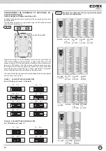
The various submenu items can be scrolled using the “
” and “
” but-
tons. The selectable submenu is indicated by the “
” arrow.
Select the item “KEYCODES” and press “
”.
To program a key:
6FUROOWKHOLVWRINH\VXVLQJWKH
“
” and “
” buttons until you find a
free key (keycode = 0);
$IWHULGHQWLI\LQJDIUHHNH\HQWHUWKHGHVLUHGFRGHDQGSUHVV
“
” to
save.
The key is memorised with the optional parameters set to the default
values.
To modify a key:
6FUROOWKHOLVWRINH\VXQWLO\RXILQGWKHULJKWRQH
0RGLI\WKHYDOXHDQGSUHVV
“
” to save. Entering 0 deletes the key.
The key is memorised with the optional parameters set to the default
values.
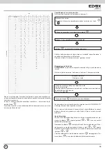
To modify the entrance panel optional data:
6FUROOWKHOLVWRINH\VXVLQJWKH
“
” and “
” buttons until you find the
desired key and press “
”.
The key submenus are:
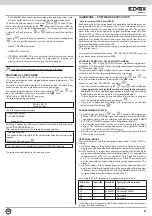
237,216(QDEOHVWKHNH\RSWLRQVWREHPRGLILHG7KHDYDLODEOHRSWLRQV
are listed in the following table:
bit
def
option
1
1
Key active. The key can be deactivated by setting this
bit to 0
2
1
Key continuous. The key is active 24/7. if this bit is set to
0, the key is active within the programmed time band.
3
0
NOT USED
4
0
NOT USED
5
1
Entering the key activates the door lock
6
0
Entering the key activates F1
7
0
Entering the key activates F2
8
0
NOT USED
Caution:
If the entrance panel is connected in parallel to other entrance
panels with both serials (terminals 1 and 6) it is possible to enable bits 5
and 6 only on one entrance panel, whereas the others must be left disabled.
A combination of actions is obtained by adding together the values of the
individual action, for example:
If Transit Time = 5 The action executed is: Transmits a double reset com-
mand and forwards the “NO KEY” command over the interphone cable riser
digibus line.
Default data reset “Factory reset” (65).
Setting this parameter to code
31830988 resets all the parameters to their default value.
Erase flash sector “Eras.Flash.SECT.” (66).
Erases the program memory
sector of the specified microcontroller.
IMPORTANT! Improper use of this parameter can damage the entrance
panel or cause malfunctions!
Number of keys from keypad (67).
Indicates the maximum of software
keys which can be inserted from keypad. The maximum number of keys
(from keypad and transponder) is 2000. These keys can be divided between
keypad and transponder, such that if for example par. 67 = 100, 1900 tran-
sponders can be used.
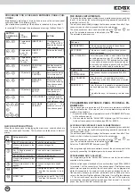
the option is active when the box associated with the bit is solid.
To modify an optional bit, select the bit using the “
” and “
” buttons.
The selected bit is indicated by the “
” arrow.
Pressing “
” changes the status of the bit.
Pressing “
” passes to the next submenu. To save the new setting press
“
”, then scroll all the submenus until the next key is reached.
EN

