background image

www.elt.es

6

2. ELECTRICAL FEATURES

2.1. Electrical parameters

The  iLC  PRO  control  gear  with  eSMART  technology  has  a  very  extensive  operating  area,  perfectly  adjusting  the 

operating point required in the design of each luminaire and each lighting system. The result is full flexibility, easily 

adapting to the continuous and fast evolution being experienced by LED technology lighting.

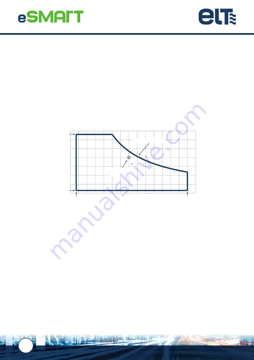
The operating area of the drivers is defined by the maximum and minimum load voltage that can be connected, by the 

maximum and minimum output current that can be programmed and by the maximum working power.

The operating point is defined by the maximum voltage of the LED module to be connected and the current which it 

is going to supply. This operating point must be within the operating area of the selected driver.

In the iLC PRO family, the operating area of one model partially overlaps with that of the higher output model, ensuring 

a continuity that effectively responds to every operating point. When the defined operating point falls within the 

operating area of several drivers, selecting the device with the lowest assigned power will provide it with the best 

electrical output values in terms of THD, power factor and efficiency; while selecting the device with the highest 

assigned power will provide a lower working temperature and as such, a longer service life. Generally, if the luminaire 

has a good thermal design, the first option is usually the recommended selection.

The iLC PRO control gear with eSMART technology permits a wide range of the supply voltage that, in addition to 

becoming a solution suited to a host of installations, guarantee stable and reliable operation in the face of fluctuations 

in the values of the mains grid voltage.

In terms of efficiency, the power factor, THD and dimming range of the iLC PRO drivers are positioned in the high 

performance segment of the lighting sector.

NOTE:

The technical specifications of each model and their corresponding data sheets can be viewed and are available for download via 

the ELT website at 

www.elt.es/en


Vo

ut

 (V)

Iout  (mA)

Operating area


Vout max

Vout min 

Iout min

Iout max

Maximum driver output


Operating point


(V module, I module)

Summary of Contents for 9916151

Page 1: ...USER GUIDE Fully PROGRAMMABLE control gear for LED modules elt elt es www elt es GU 001 05 18 EN ORC 5 ...

Page 2: ... 2 Overload and open circuit protection 9 4 3 Thermal protection 9 4 4 Out of range mains voltage protection 10 4 5 Shock wave protection 10 5 FUNCTIONALITIES 11 5 1 Adjustable output current AOC 11 5 2 LED module thermal protection MTP 12 5 3 LED module constant lumen output CLO 13 5 4 LED module end of life alarm EOL 14 5 5 Programmable start up time PST 14 5 6 Monitoring parameters and events 1...

Page 3: ...es 30 8 3 Connecting the drivers 30 8 4 Protective switches 32 9 ELECTROMAGNETIC COMPATIBILITY 34 10 MECHANICAL FEATURES 35 11 DRIVER CONFIGURATION 36 11 1 iSOFT 36 11 2 iProgrammer 36 11 3 Quick start guide 37 11 4 Factory default configuration 38 12 MARKINGS AND INDICATIONS 39 13 APPLICABLE STANDARDS 40 14 PRODUCT WARRANTY 41 15 DISCLAIMER 42 ...

Page 4: ...oint accompanied by the best operational features and maximum energy saving which helps reduce both economic costs and CO2 emissions into the atmosphere throughout the lifetime of the street lighting system These drivers can be used in an infinite number of applications such as street lighting roads monuments sports facilities and industrial premises 1 3 Classification and symbols The nomenclature...

Page 5: ...de toestablish exceptions to the stand alone dimming during a specific period Parking mode light regulation via presence detectors ActiDIM Parking combines stand alone dimming with presence detectors LineSwitch lineswitch dimming MainsDIM head end dimming by varying the mains voltage ON OFF no regulation Compatible with the STELARIATM remote street lighting management system Short circuit overload...

Page 6: ...he defined operating point falls within the operating area of several drivers selecting the device with the lowest assigned power will provide it with the best electrical output values in terms of THD power factor and efficiency while selecting the device with the highest assigned power will provide a lower working temperature and as such a longer service life Generally if the luminaire has a good...

Page 7: ...e functional earth is set out in the following table Functional earth Input voltage DALI 0 10V LED module external NTC STELARIA Functional earth X Double Double Double Double Input voltage Double X Main Main Double DALI Double Main X Main Double 0 10V Double Main Main X Double LED module external NTC STELARIA Double Double Double Double X NOTE When the devices are built into luminaires the cabling...

Page 8: ...ace indicated on the casing of each driver once thermal stability has been achieved NOTE The eSMART drivers from the PRO range incorporate a diagnostic mode that indicates the internal temperature value of the driver This is for guidance purposes only as it does not necessarily coincide with the tc value 3 2 Ambient temperature ta The eSMART drivers have been designed to be able to operate within ...

Page 9: ...ply Should overloads or open circuit events repeat over time with a high level of frequency or if such events persist protection mode will not automatically reset and it will be necessary to disconnect the mains power for at least a few seconds If the driver is connected at a load lower than that permitted for the operating area it will flicker as long as it remains connected 4 3 Thermal protectio...

Page 10: ...urges of 380Vac for 2 hours extreme care must be taken to avoid this type of situation 4 5 Shock wave protection Drivers equipped with eSMART technology from the PRO range are designed to offer improved protection of the supply terminals against shock waves such as those caused by radio storms They benefit from levels of protection in both differential and common modes that are higher than the min...

Page 11: ... feature that configures the nominal value of the output current from a driver with eSMART technology The output current value selected is understood to be the nominal value used to achieve 100 of the light level in any of the selected dimming modes that can be programmed within the entire permitted range ...

Page 12: ...e LED module if the read temperature exceeds a value defined as the cut off temperature In the event that the LED module switches off because it has reached the cut off temperature value the driver automatically switches back on at the maximum dimming level when the read temperature is 5ºC below the start temperature So that the values of the measured temperatures are correct and can be handled by...

Page 13: ...working Based on this information a table can be defined to incrementally assign an output current value for each operating interval so that the loss of LED module lumen output during that period is compensated The output current value can be assigned in increments of 1 within a range from 0 to 100 where 100 is the value defined by the AOC The intervals can be configured in steps of 500 hours To s...

Page 14: ... LED module has to be selected in addition to the actual time that the module has been working The driver will make the LEDs flicker for 3 seconds after power on when the actual operating time reaches the expects lifetime after which it will continue its normal operation 5 5 Programmable start up time PST This feature is able to configure a smooth and pleasant start up avoiding an abrupt sensation...

Page 15: ...e the peak and width values of the inrush current 5 6 Monitoring parameters and events Control gear equipped with eSMART technology records numerous events in its non volatile internal memory along with the maximum and minimum values of different parameters and operating times in different modes relating to the control gear itself as well as to the LED modules its drives Real time data recorded an...

Page 16: ...methods Dimming is achieved through the amplitude modulation AM of the output current obtaining flicker free light at each regulation point The main features of each method are explained below 6 1 DALI mode DALI Digital Addressable Lighting Interface is a digital and addressable communication interface for lighting systems standardised in line with EN 62386 that guarantees the correct operation be...

Page 17: ...of an analogue control signal that reaches the drivers via an additional two wire control line whose positive and negative polarity must be observed when making the connection This one way system in which the control information only flows from the controller towards the control gear is not addressable given that every device connected by cable to the control line reacts to a set point The analogu...

Page 18: ...ice is expected to work in extreme temperature ranges The response of the 1 10V dimming differs slightly to the 0 10V In 1 10V dimming the maximum dimming level is obtained by leaving the control terminals in open circuit or with a signal equal to 10V This is the 100 level and cannot be configured The minimum level however is obtained by short circuiting the control terminals or via a signal lower...

Page 19: ...ration of each night is defined as the time measured from when the street lighting is switched on to the time it is switched off NOTE When the lighting is switched on for less than 4 hours for example to carry out maintenance tasks or during power outages and in cases where it is on for more than 20 hours the control gear does not memorise that period as a night and therefore does not take it into...

Page 20: ...cific location For example in summer the initial dimming parameters defined for the period up until midnight are cancelled so that the driver operates at maximum power up to that point before continuing to follow the profile established under normal ActiDIM mode This function offers added value to the standard ActiDIM mode as it allows the luminaire to operate with two different behavioural patter...

Page 21: ...on the hours of dawn and dusk calculated by the astronomical clock algorithm built into the configuration software There may be one minute of difference to the astronomical clocks of each installation In installations where switching the street lighting on and off is significantly ahead or behind the time set by the installation s astronomical clock or if other methods such as photocells are used ...

Page 22: ...logy control gear is able to connect presence detection sensors that return the detection signal by means of a dry contact connected to the 1 10V control terminals or via a voltage level that has to be connected to the DALI control terminals The type of output offered by the sensor to be used must first be selected using the iSOFT configuration tool Other parameters to configure are the dimming le...

Page 23: ...nergy saving profile such as the one offered by ActiDIM but which need a high light level when a presence is detected for example on zebra crossings Level 0 10 20 30 40 50 60 70 80 90 100 19 1hs 1 47hs 8 33hs 20 21 0 1 22 23 3 2 4 6 5 8 7 Time with presence NDT No detection time Level A NOTE If in the event a presence is detected level A configured by the Parking mode is lower than the actual leve...

Page 24: ... line switch option based on a dry contact is selected the driver connection has to be made in the 1 10V control terminals If the chosen option is a line switch with mains voltage the connection has to be made in the DALI control terminals In both cases the required dimming level can be configured when the signal in the control line is detected or when it is not receiving As a result the installat...

Page 25: ...is easy and intuitive to configure in a graphic format via the iSOFT configuration software NOTE The use of this dimming method is recommended for installations with a peak value factor of 1 4142 supply voltages with peak factors other than the above will cause variations to the measurement of the mains voltage made by the control gear and as such will create an advanced or out of phase action as ...

Page 26: ...on is required This mode configures the PST parameter for enhanced visual comfort while the luminaire powers on If the user configures the driver with an output current below 200mA by means of the AOC functionality the driver will enter ON OFF mode by default and no type of regulation will be allowed ...

Page 27: ...oring of the luminaire s operation by means of the driver This powerful and integrated solution incorporates the software hardware and communications necessary to remotely control and operate outdoor lighting systems To be able to use this system each luminaire has to be equipped with an eSMART driver in the version fully compatible with STELARIA as well as with a STELARIA wireless communications ...

Page 28: ...ly and to the STELARIA communications port built into the driver as shown in the following diagram To give the user operational control of the luminaires STELARIA offers an online lighting control based on a user friendly reliable and secure web application This can be accessed at all times and from anywhere from any device connected to the internet providing accurate and immediate control of the ...

Page 29: ...d system events Register of operating hours Simple management and classification of luminaires by city street coordinates type Maintenance planning Administration of multiple users roles and installations Acquisition and handling of data in the cloud The architecture and technologies of the STELARIA system can also be personalised on request in order to acquire process and visualise data originati...

Page 30: ...on and is suitable for installation in both Class I and Class II luminaires Insofar as it is possible they must be installed away from heat sources and be fitted to maximise heat dissipation 8 3 Connecting the drivers To ensure that the eSMART drivers are correctly connected and work properly the following instructions must be taken into account Do not exceed the permitted ranges for the electrica...

Page 31: ...tween them by using serrated washers and sufficiently tightened screws ensuring that the connecting cables are as short as possible to minimise inductances and thereby maximise their efficacy In Class I luminaires the protective earth conductor is strictly compulsory Connect the protective earth to the chassis and to the internal metal parts In Class II luminaires ELT recommends installing an equi...

Page 32: ... which can be viewed on the specific data sheets for each reference have been empirically obtained using the set up and measurement method proposed under the draft standard IEC 63129 for a 277V AC reference power grid as defined under NEMA standard 410 with a line impedance of 450mΩ and 100 H The inrush current values of the control gear will reduce thereby increasing the number of drivers to be c...

Page 33: ...at the protective single circuit trip switches can be appropriately sized In three phase modules leakage currents are compensated by balancing the distribution of the luminaires connection between the three phases while for single phase networks the maximum number of luminaires that can be connected to each switch has to be calculated NOTES Typically a maximum of 35 luminaires can be connected in ...

Page 34: ...t be physically separated and never crossed Running a cable over or sticking it to the control gear is not recommended ELT recommends that the functional earth of every metallic component of the luminaire is connected to the protective earth in Class I luminaires even though this connection is not designed to protect from electric shocks The eSMART control gear is of a build to use type This means...

Page 35: ...35 www elt es 10 MECHANICAL FEATURES Ø 4 2 140 5 129 1 74 3 50 10 8 32 iLC PRO XT format 38 3 Ø 4 5 156 8 144 6 93 4 78 5 iLC PRO XR format ...

Page 36: ...ilitating the creation of templates to configure functionalities and the required operating mode that best adapts to your application The iSOFT tool and its user guide including a step by step explanation of every detail to install use and configure the drivers is available to be downloaded for free via the following link www elt es en download isoft software 11 2 iProgrammer Together with iSOFT s...

Page 37: ...o use NOTE As the connection layout illustrates the driver has to be connected to the power grid External power supply Alimentación eléctrica externa Optional for more than 4 control gears Opcional para más de 4 equipos EIAJ 2 connector for 4 control gears Conector EIAJ 2 para 4 equipos de control DA L N DA USB 2 0 Overload External DALI power supply Communication Internal DALI power supply Power ...

Page 38: ...tionalities Adjustable Output Current AOC 700 mA LED Module Thermal Protection Deactivated Constant Lumen Output CLO Deactivated Module End of Life Alarm EOL Deactivated Programmable Start Up PST Deactivated Parameter monitoring Always activated Operating modes ON OFF Deactivated DALI Deactivated 1 10V Deactivated 0 10V Deactivated ActiDIM Activated Tourist ActiDIM Deactivated Parking mode Corrido...

Page 39: ...with no additional casing Lamp control gear with double or reinforced insulation between the primary and secondary circuits resistant to short circuits 1 Lamp control gear with double or reinforced insulation between the primary and secondary circuits resistant to short circuits and with Safety Extra Low Voltage SELV 1 Device with Safety Extra Low Voltage SELV 100 Device with over temperature prot...

Page 40: ...magnetic compatibility EMC Part 3 3 Limits Limitation of voltage changes voltage fluctuations and flicker in public low voltage supply systems for equipment with rated current 16 A per phase and not subject to conditional connection EN 55015 Limits and methods of measurement of radio disturbance characteristics of electrical lighting and similar EN 61547 Equipment for general lighting purposes EMC...

Page 41: ...h current IEC and or EN international standards and the particular specifications provided by ELT in this user guide Correct usage handling and storage of the product to guarantee the absence of third party damage This warranty excludes claims under which ELT is not liable for defects or faults and specifically those which fall within any of the following cases Incorrect handling abusive use or an...

Page 42: ...y are the best known technical or commercial options ELT accepts no claim based on any damage arising from the application of the above recommendations The data contained in this user guide that refers to technical features and product testing is for information purposes only and is not considered to be an official certification that supports the release of the end product into which the product t...

Page 43: ...xport Tel 34 976 573 660 Fax 34 976 574 960 e mail cs export elt es Customer service National Tel 34 976 573 660 Fax 34 976 574 960 e mail cs nacional elt es EASTERN EUROPE AND CIS COUNTRIES Area Sales Manager VICTORIA SYCHEVSKA Decin Czech Republic Tel 420 725 937 825 Email vsychevska elt es www elt es Innovation in lighting technology ...

Reviews: