


POLARIS 10●15●20●30●40●60●80●100●120●160
TRIPHASE-TRIPHASE
Rev. 04 – 06 December 2016
11
3.9 UPS parallel Installation
The following sections introduce the installation procedures specified to the parallel system.
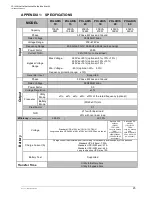
3.9.1 Cabinet installation
Connect all the UPS needed to be put into parallel system as below picture.
Make sure each UPS input breaker is in “off” position and there is no any output from each UPS
connected. Battery groups can be connected separately or in parallel, which means the system itself
provides both separate battery and common battery.
WARNING!
Make sure the N, A (L1), B (L2), C (L3) lines are correct, and grounding is well connected.
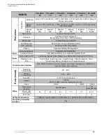
3.9.2 Parallel cable installation
Shielded and double insulated control cables available must be interconnected in a ring configuration
between UPS units as shown below. The ring configuration ensures high reliability of the control.
3.9.3 Requirement for the parallel system
A group of paralleled UPS behaves as one large UPS system but with the advantage of presenting
higher reliability. In order to assure that all UPS are equally utilized and comply with relevant wiring rules,
please follow the requirements below:
1) All UPS must be of the same rating and be connected to the same bypass source.
2) The outputs of all the UPS must be connected to a common output bus.
3) The length and specification of power cables including the bypass input cables and the UPS output
cables should be the same. This facilitates load sharing when operating in bypass mode.
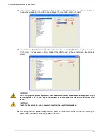
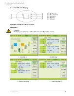
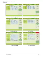
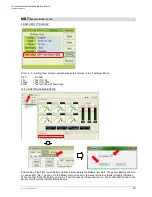
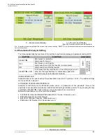
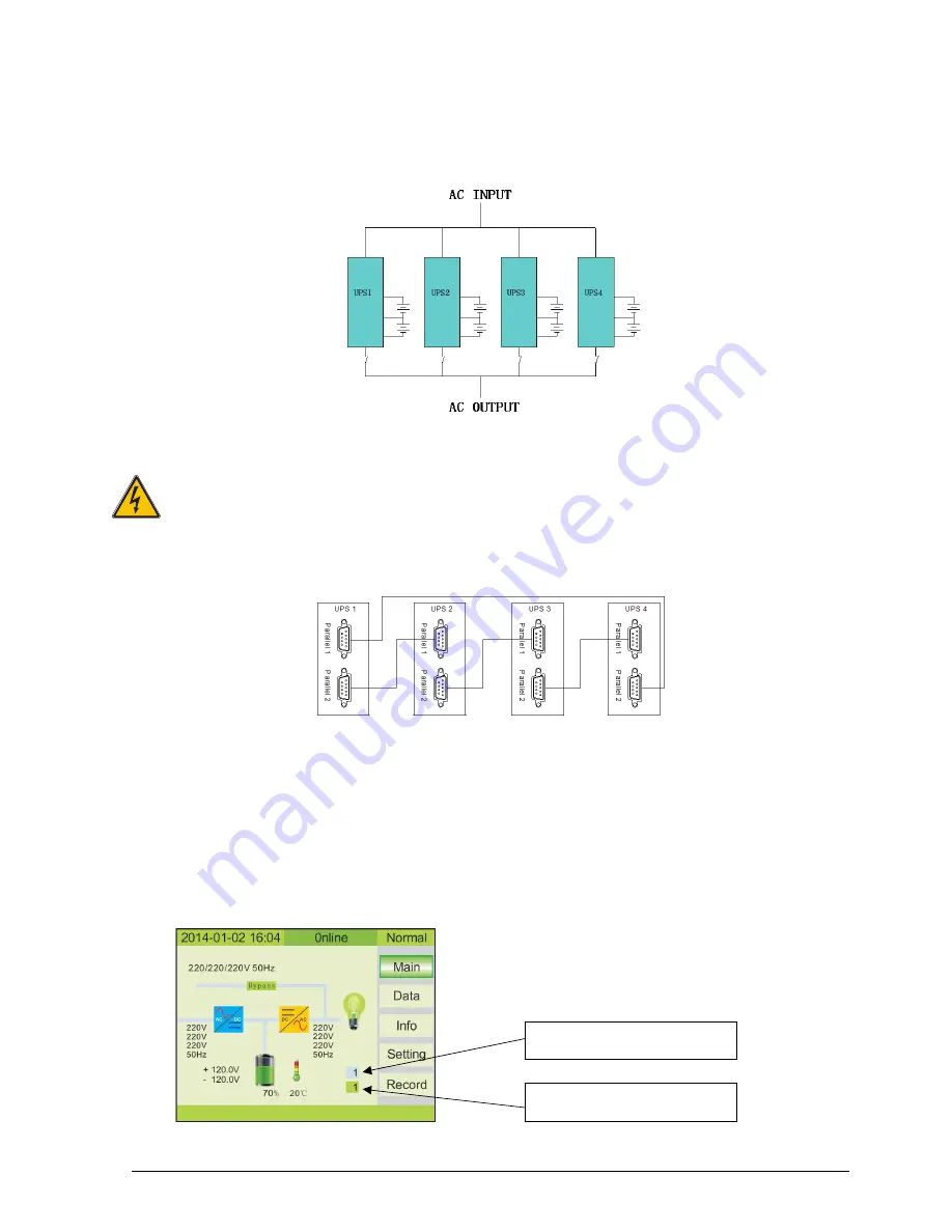
3.9.4 On screen display
Parallel ID number
(light blue)
System ID number
(green)


