background image

Index

Features ..............................................................4

Description..........................................................4

Part Number ........................................................5

Menu Structure ............................................... 6-7

Connection Diagram ...........................................8

Setup Instructions ...............................................9

Limit Switches...................................................10

Setup i-Learning Steps......................................11
Menu 1 – Auto Close ........................................12

- Normal Auto Close

 ...................................12

- Auto Close with Photoelectric Trigger

 ......12

- Auto Close after an Open Obstruction

 ......12

-  Auto Close after Power Restored.

..............13

-  Normal Auto Close on  

Sequential Obstructions

 ...........................13

-  Auto Close Only when  

Fully Opened

 ............................................13

- Auto Close Only at Night

 ..........................13

Menu 2 – Pedestrian Access Features ........ 13-14

Menu 3 – Input Functions .................................14

Menu 4 – Photoelectric Beam ...........................15

Menu 5 – Relay Output Functions .....................16

-  Lock/Brake Output

 ....................................17

- Courtesy Light

 ..........................................17

- Service Call Output

 ..................................18

- Strobe or Warning Light

 ...........................18

Menu 6.1 – Lock/Brake Output Modes..............19

-  Open Lock/Brake Activation

 .....................19

-  Close Lock/Brake Activation

 .....................19

-  Open Pre-Lock/Brake Activation

 ...............19

-  Close Pre-Lock/Brake Activation

 ..............19

Menu 6.2 – Courtesy Light Output Mode ..........20

Menu 6.3 –  Strobe (Warning) 

Light Output Mode .........................20

-  Pre-Open Strobe Light Activation

 .............20

-  Pre-Close Strobe Light Activation

 ............20

Menu 6.4 – Service Call Output Mode ..............21

Menu 7 – Special Features................................22

-  Remote Control Open Only

 .......................22

-  Holiday Mode

 ...........................................22

-  Energy Saving Mode

 ................................22

-  Automatic Stop / Open on Closing

 ...........23

Receiver Channel 2 Options

 .....................23

Press and Hold on Open & Close Inputs

 ..23

Window and Louvre Mode

 .......................23

Menu 8 – Leaf Delay .........................................23

-  Open Leaf Delay

 .......................................23

- Close Leaf Delay

 ......................................23 

- Close Leaf Delay on Mid Open

 .................23

Menu 9 –  Motor 1 Obstruction  

Detect Margins..................................24

-  Margin Example

 .......................................24

Menu 10 –  Motor 2 Obstruction  

Detect Margins................................25

-  Margin Example

 .......................................25

Menu 11 –  Motor Speed, Slow Speed 

Area and Reverse Time ....................26

-  Open and Close Speed

 .............................26

-  Slow Speed

 ..............................................26

-  Slow Speed Area

 ......................................26

-  Obstruction Stop Reverse Delay Time

 ......26

Menu 12 –  Anti-Jam, Electronic Braking and 

Open/Close Obstruction Operation .27

Menu 13 – i-Learning .......................................28

Menu 14 –  Password ........................................28

Menu 15 –  Operational Records........................28

-  Event History ............................................

28

-  Displays Gates/Doors Operations 

and Current Levels

 ...................................28

Menu 16 –  Tools ...............................................29

-  Number of Motors

 ....................................29

-  Set the Supply Voltage

 .............................29

Resets Controller & Test Inputs

 ................29

Travel Timer for Slip Clutch Motors

..........29

Solar Mode and Fuse Type

 .......................29 

Day and Night Sensitivity Adjustment

 ......29 

Slow Speed Ramp Down Time

 .................29

Accessories .......................................................30

- Battery Charger and Solar Applications

 ....30

- Backup Batteries

 .......................................30

- Keyring Remotes & Photoelectric Beams

 .31

- Strobe Lights

 ............................................31

3

www.elsema.com

Summary of Contents for Eclipse MC

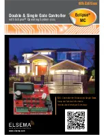
Page 1: ...ema com MC Controller for Double and Single Gates Setup and Technical Information Includes latest Intelligent Technology Double Single Gate Controller with Eclipse Operating System EOS 6th Edition Ecl...

Page 2: ...ods purchased shall unless otherwise agreed in written pass to the buyer upon delivery of the goods Any figures or estimates given for performance of goods are based upon the company s experience and...

Page 3: ...1 Menu 7 Special Features 22 Remote Control Open Only 22 Holiday Mode 22 Energy Saving Mode 22 Automatic Stop Open on Closing 23 Receiver Channel 2 Options 23 Press and Hold on Open Close Inputs 23 Wi...

Page 4: ...s doors and barriers It uses a large 4 line LCD screen showing live reading of the motor performance and status of all inputs and outputs The MC controller is not just the next generation but the indu...

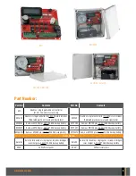
Page 5: ...24 Volt 2 6Ah backup battery MC12E2 Same as MC12E plus 12 Volt 2 6Ah backup battery MC24E7 Same as MC24E plus 24 Volt 7 0Ah backup battery MC12E7 Same as MC12E plus 12 Volt 7 0Ah backup battery MC24E1...

Page 6: ...arning Light 5 2 Relay Output 2 11 1 Open Speed 11 2 Close Speed 14 1 Enter Password 14 2 Delete Password 16 1 No of Motors 1 2 16 2 Supply Voltage 3 1 PE Polarity 3 2 Limit Sw Polarity 9 1 M1 Open Ob...

Page 7: ...Fully Open 11 6 Stop Rev Delay Time 11 7 EXIT 14 3 EXIT 16 3 Reset Factory Default 16 4 Test Inputs 3 3 Stop Input Polarity 9 3 M1 Slow Speed Obstruct 12 3 M2 Open Anti Jam 12 4 M2 Close Anti Jam 12 5...

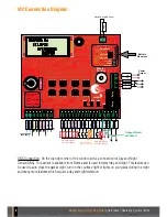
Page 8: ...lts AC Model MC Designed by ELSEMA IN AUSTRALIA Normally Closed User can change AC Supply DNS Day and Night Sensor ELSEMA Normally Open User can change Eclipse operating system Powered By Receiver Pro...

Page 9: ...using mechanical stops move to the Setup i Learning Steps Skip Limit Switch section Normally Closed User can change Fuse Relay Open Close Stop Open Limit Common Motor 1 Close Limit Motor 1 Open Limit...

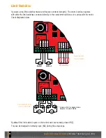
Page 10: ...NO during the setup steps Normally Closed User can change Fuse AC Supply 24 12 Volts AC Model MC Designed by ELSEMA IN AUSTRALIA AC Supply AC Supply Motor 1 Motor 1 AC Supply AC Supply Motor 2 Motor 2...

Page 11: ...instructions displayed 4 The MC control card will open and close the gates or doors several times to learn the load and travel distances This is the auto profiling using latest intelligent technology...

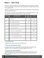
Page 12: ...Open Obstruction Off 1 60 seconds 1 4 Auto Close after Power Restored Off 1 60 seconds 1 5 Normal Auto Close on Sequential Obstructions 2 Min Off Max 5 1 6 Auto Close Only when Fully Opened Off Off On...

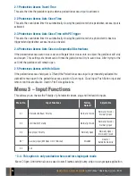
Page 13: ...nnected and the sensitivity Menu 16 8 is set correctly the auto close will only work at night Menu 2 Pedestrian Access There are several types of Pedestrian access modes Pedestrian access opens the ga...

Page 14: ...estrian Access with Hold Gate If the pedestrian access hold gate is ON and the Pedestrian access input is permanently activated the gate will remain open in the pedestrian access position Open input C...

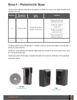
Page 15: ...e door on open close cycle PE Beam stops and closes gate door on open cycle 4 2 Exit The factory default for the PE beam input is normally closed but this can be changed to normally open To change it...

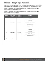
Page 16: ...brake release function Output 2 is a voltage free relay output with common normally open and normally closed contacts Factory default is courtesy light function Menu No Relay Output Function Factory D...

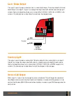
Page 17: ...t 2 is a voltage free relay contact with common normally open and normally closed contacts Having it voltage free allows you to connect either 12VDC AC 24VDC AC or 240VAC supply to the common The norm...

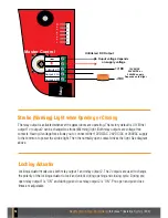
Page 18: ...light See diagram above Relay R e c e i v e r Master Control Output 2 C Output 2 NC Output 2 NO Unfiltered DC Output Ouput voltage depends on supply voltage if DC if DC 240VAC supply 24VAC DC or Depe...

Page 19: ...utput is activated Factory default is 2 seconds Setting it to Hold means the output is activated for the total travel time in the open direction 6 1 2 Close Lock Brake Activation This sets the time th...

Page 20: ...he strobe Warning mode can be configured in different ways Menu No Strobe Warning Light Mode Factory Default Adjustable 6 3 1 Pre Open Strobe Warning Light Activation Off 0 30 seconds 6 3 2 Pre Close...

Page 21: ...6 4 1 Service Counter Off Min 2000 to Max 50 000 6 4 2 Exit Menu 6 5 Locking Actuator Output Mode The time for which relay output 1 turns on before the gate door starts to open and the time for which...

Page 22: ...n 7 9 Wind Loading Off Off On 7 10 Exit 7 1 Remote Control Open Only By default the remote control allows the user to open and close the gates doors In public access areas user should only be able to...

Page 23: ...n Mid Stop By default motor 1 will always have delay when closing even if the gate is not fully open When disabled both motor 1 and motor 2 will start closing at the same time only when not fully open...

Page 24: ...me Factory Default Adjustable 9 1 Open Obstruction Margin 1 Amp 0 5 6 0 Amps 9 2 Close Obstruction Margin 1 Amp 0 5 6 0 Amps 9 3 Open and Close Slow Speed Obstruction Margin 1 Amp 0 5 6 0 Amps 9 4 Obs...

Page 25: ...rgins and Response Time Factory Default Adjustable 10 1 Open Obstruction Margin 1 Amp 0 5 6 0 Amps 10 2 Close Obstruction Margin 1 Amp 0 5 6 0 Amps 10 3 Open and Close Slow Speed Obstruction Margin 1...

Page 26: ...d This sets the speed at which the gates doors will travel If the gate door is travelling too fast reduce this value 11 3 Slow Speed This sets the speed at which the gates doors will travel in the slo...

Page 27: ...ature applies a reverse voltage for a very short time It will prevent the motor from jamming up the gates doors so it is easy to disengage the motors for manual operation 12 3 and 12 4 Motor 2 Open an...

Page 28: ...t Obstruction 15 2 Displays Gates Doors Operations and Current Levels This displays the number of open cycles close cycles pedestrian cycles open obstructions close obstructions and both motor current...

Page 29: ...to the controllers inputs UPPERCASE means input is activated and lowercase means input is deactivated 16 5 Travel Timer for Slip Clutch Motors This allows you to use the controller with travel timers...

Page 30: ...kits are available WARNING To use the control card in a solar application you must set the correct voltage input in the Tools Menu 16 2 This will disable the automatic voltage sensing which could cau...

Page 31: ...aFOB keyring remotes ensure your gates or doors are secure Visit www elsema com for more details Photoelectric Beam Elsema has several types of photoelectric beams including retro reflective and throu...

Page 32: ...ELSEMA PTY LTD 31 Tarlington Place Smithfield NSW 2164 Australia P 02 9609 4668 F 02 9725 2663 W www elsema com...

Reviews: