background image

- 27 -

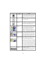
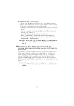
To present the material with a little half
tone such as documents.
Images with sharp characters and lines
contrasty with background can be
obtained.
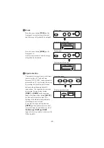
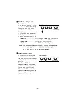
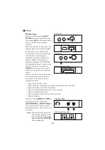
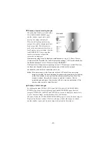
When the contrast button 

[CONTRAST]

on the operation panel is pressed, the
indicator lamp lights up, and the image
becomes contrasty.
When the contrast button 

[CONTRAST]

is pressed again, the indicator lamp goes
out, and the image is reset to the normal
condition.

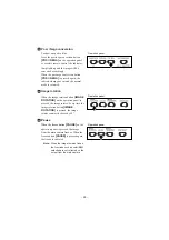
Operation panel

Contrast

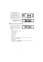
White Balance

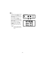
Operation panel

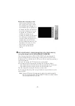
The camera of the Presenter
automatically adjusts the shooting color
balance (AUTO mode). However,
depending on the color arrangement of
document or the like, this color balance
may be lost. In such case, shoot the stage
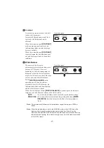
surface, and press the white balance
button 

[WHITE BALANCE]

on the

operation panel. Then, the mode is
switched to the ONE-PUSH mode, the
indicator lamp blinks and then lights up,
and the white balance is fixed.

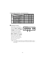
When the white balance button 

[WHITE BALANCE]

is pressed again, the indicator

lamp goes out, and the mode returns to the AUTO mode.

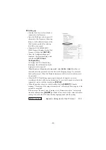
AUTO

.............To set the white balance in the auto follow mode (initial setting).

ONE-PUSH

....To set the push-set white balance. By pressing the button 

[WHITE

BALANCE]

, the white balance for the then color temperature is

fixed.

Note: The automatically followed color temperature ranges from approx. 3000k to

8000k.

Note: When the white balance is set to the MANUAL mode on the OSD, the white

balance is fixed, and the indicator lamp remains lighting. When the white
balance button [WHITE BALANCE] on the operation panel is pressed while the
indicator lamp is lighting, the indicator lamp goes out, and the mode is switched
to the AUTO mode.

Summary of Contents for HV-8500SX

Page 1: ...INSTRUCTION MANUAL VISUAL PRESENTER Please read this instruction manual carefully before using this Visual Presenter and keep it for future reference VISUAL PRESENTER HV 8500SX cev fr ...

Page 2: ...OPERATION PROCEDURES 19 Simple steps for presenting printed material 19 Simple steps for showing transparent material such as overhead transparencies or slide film 20 7 VARIOUS FUNCTIONS 21 Lighting 21 Zoom 22 Input selection 22 Table of Video and Audio in out Terminal Selections 23 Output to the monitor 23 Table of Corresponding Signals 24 Electronic enlargement 25 Color B W selection 25 Posi Neg...

Page 3: ...trol 41 FTP client function 41 Setting up 42 Operation 43 FTP server functions 43 telnet server functions 43 Appendix 44 Setting items of the network 44 Setting items of the FTP client 44 Specifications of the FTP server 45 10 RS 232C SPECIFICATIONS 46 Setting up 46 Cable connection 46 Table of the communication commands 47 Data format specifications 48 Trasnmission Command PC Visual Presenter 49 ...

Page 4: ...9 Carryng Handle Press this button to raise fold the column Usually this panel is kept inside the main body When the PUSH part is pushed this panel becomes ready for operation 6 Lighting Unit Arm 5 Lighting Unit Front Panel 18 Auto Focus Button Name Function Reference Page 16 P 20 P 21 Lamp Buttons Zoom Buttons Auto Focus Button To turn ON OFF the lighting To change the image size To focus automat...

Page 5: ...olor B W Selection Button To present black and white material such as documents Posi Nega Conversion Button To show negative films Image Rotation Button To rotate the image Every time this button is pressed the image rotates counterclockwise by 90 Freeze Button To freeze the image temporarily White Balance Button Auto One Push To change the mode between AUTO and ONE PUSH Contrast Button To make ch...

Page 6: ...is output when these terminals are connected to the NTSC PAL monitor e g TV monitor Ethernet Terminal Ethernet To connect the Ethernet cable when the network function is used Analogue RGB out Terminal OUTPUT RGB OUT Image is output when this terminal is connected to RGB input equipment e g liquid crystal projector multi sync monitor USB Terminal USB To connect the USB cable attached to transfer th...

Page 7: ...deo in Terminal 1 Video signal from this terminal is output through the analogue RGB out terminal when the input selection is set at RGB1 Video in Terminal 2 Video signal from this terminal is output through the analogue RGB out terminal when the input selection is set at RGB2 Audio in Terminal 1 Audio signal from this terminal is output through the audio out terminal when the input selection is s...

Page 8: ...o close the AUTO iris 48 P 28 IRIS NORMAL To reset the AUTO iris to the initial value 49 P 29 P 30 FOCUS NEAR To move the focus near 50 P 29 P 30 FOCUS FAR To move the focus far 51 P 19 P 22 P 29 ZOOM TELE To zoom in 52 P 19 P 22 ZOOM WIDE To zoom out 53 P 22 INPUT To change the input system 54 P 20 P 21 LAMP To turn ON OFF the lamp 55 P 30 MOVE To call the operating status of the Presenter saved ...

Page 9: ...7 m 23 ft or less from the light receiving area to the front of the wireless remote control Angle Approx 30 degrees or less from the light receiving area to the front of the wireless remote control rightward leftward upward and downward respectively 2 WIRELESS REMOTE CONTROL Preparation Remove the battery case cover by pressing downward on the OPEN mark part in the direction as indicated by the ar...

Page 10: ...enlargement Right button When this button is clicked when the pointer is in display the electronic image enlargement function is activated with the position indicated by the pointer as a center Note When the right button is clicked on the OSD menu the menu functions are given priority Reference Page Electronic enlargement P 25 Note When using the mouse connect the mouse before turning ON the power...

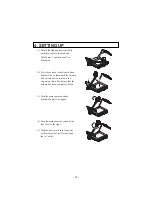
Page 11: ...button and raise the column until the column lock release button returns to the original position Make sure that the column has been completely locked 3 Turn the main camera head as illustrated until it is stopped 4 Turn the main camera head until the lens faces to the stage 5 Plug the power cord into the power cord receptacle of the Presenter and the AC outlet ...

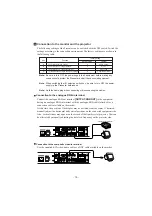
Page 12: ...connected equipment side Also vertical stripes may appear on the screen of the liquid crystal projector That can be alleviated by manually adjusting the dot clock frequency on the projector side Connection to the monitor and the projector Note Be sure to turn OFF the power supply to all equipment before making any connections to protect the Presenter and all the connected equipment Note When switc...

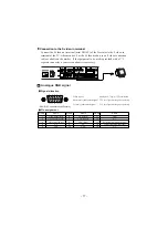
Page 13: ...ed 7 GND Green 8 GND Blue 9 N C 10 GND Pin No Name 11 GND 12 N C 13 Horizontal synchronized signal 14 Vertical synchronized signal 15 N C AC IN MOUSE INPUT S VIDEO VIDEO L AUDIO R AUDIO L R 1 AUDIO L R 2 RGB OUT RGB2 RGB1 OUTPUT ON OFF POWER USB Ethernet RS 232C DC12V Monitor Connection to the S video in terminal Connect the S video out terminal mini DIN 4P of the Presenter to the S video in termi...

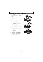
Page 14: ... illustrated position before storing Storing the main camera head in any other position may damage the stage surface or the lens 3 Press the column lock release button and fold down the main column Note The illustration shows the right storage position of the column Never apply excessive force to the column 4 Fold down the lighting unit arms 5 and 6 Be sure to fold down arm 5 first as per the illu...

Page 15: ...he stage Adjust the image size according to the object size using the zoom buttons TELE WIDE on the front panel or the zoom buttons TELE WIDE on the wireless remote control while watching the image on the TV monitor 3 Press the auto focus button AUTO FOCUS on the front panel or the auto focus button AF on the wireless remote control Note The auto focus function works up to a height of approx 10cm ...

Page 16: ...nversion button POSI NEGA on the operation panel to change the mode to N Negative 3 To turn OFF the base light press the base button BASE on the front panel or the lamp button LAMP on the wireless remote control again IRIS OPEN LAMP Wireless remote control Front panel Operation panel Simple steps for showing transparent material such as overhead transparencies or slide film IRIS OPEN LAMP Wireless...

Page 17: ... time the lamp button LAMP on the wireless remote control is pressed lighting is switched in a cycle of the lighting unit lights up the base light lights up the base light goes out The lighting unit lights up when the power supply is turned ON To turn OFF the lamp press the button for the respective lamp Lighting 7 VARIOUS FUNCTIONS IRIS OPEN LAMP Front panel Wireless remote control Note It is imp...

Page 18: ...lamp indicates which input is now selected Every time the input selection button INPUT on the wireless remote control is pressed input is switched in a cycle of the Main RGB1 RGB2 Input selection is possible as shown in the following table INPUT AF Operation panel Wireless remote control Input selection TELE WIDE ZOOM Front panel Wireless remote control TELE WIDE ZOOM Front panel Zoom Wireless rem...

Page 19: ...d RGB2 can be output to the NTSC PAL monitor if their frequencies are among the listed in the table at the next page Operation panel Select the signal to be output to the NTSC PAL monitor When the monitor output button RGB1 or RGB2 on the operation panel is pressed while RGB1 or RGB2 is selected for the input selection the indicator lamp lights up and the image from the equipment connected to the ...

Page 20: ...8 363 56 476 60 023 68 677 67 500 60 000 85 938 63 981 79 976 91 146 75 000 81 250 87 500 93 750 106 250 35 000 49 725 60 241 68 682 24 825 85 080 31 500 31 500 35 500 25 175 31 500 31 500 36 000 36 000 40 000 50 000 49 500 56 250 65 000 75 000 78 750 94 500 108 000 108 000 148 500 108 000 135 000 157 500 162 000 175 500 189 000 202 500 229 500 30 240 57 283 80 000 100 000 21 052 640 640 720 640 6...

Page 21: ... of the image press the button MAGNIFICATION on the operation panel When double magnification is selected the indicator lamp lights up The image can be enlarged only within the shooting area of the main camera The mouse can be operated as follows Left button To scroll the image according to the dragging of the mouse while holding down the left button Mouse wheel To scroll up down the enlarged scre...

Page 22: ...pressed again the freeze is canceled Note When the image remains frozen the functions such as color B W selection are not reflected on the output from the main camera Operation panel Image rotation Pause Operation panel Posi Nega conversion To show a negative film Press the posi nega conversion button POSI NEGA on the operation panel or wireless remote control the indicator lamp lights up and the ...

Page 23: ...ance button WHITE BALANCE on the operation panel Then the mode is switched to the ONE PUSH mode the indicator lamp blinks and then lights up and the white balance is fixed When the white balance button WHITE BALANCE is pressed again the indicator lamp goes out and the mode returns to the AUTO mode AUTO To set the white balance in the auto follow mode initial setting ONE PUSH To set the push set wh...

Page 24: ...s open button IRIS OPEN on the wireless remote control and the iris will open Press the iris button CLOSE on the operation panel or the iris close button IRIS CLOSE on the wireless remote control and the iris will close Press the iris normal button IRIS NORMAL on the wireless remote control and the initial setting will be resumed Note When the image looks dark adjust the brightness with iris contr...

Page 25: ...auto focus botton However the objects listed below may not be brought into focus in the auto focus mode In these cases use the manual focus mode INPUT AF Front panel Wireless remote control TELE WIDE ZOOM Front panel Wireless remote control If the focus button NEAR or FAR on the front panel or the focus button FOCUS NEAR or FOCUS FAR on the wireless remote control is pressed during the auto focus ...

Page 26: ...VE on the wireless remote control is pressed the Presenter is set to the preset status 2 How to preset When the preset button PRESET on the wireless remote control is pressed the current status of the Presenter is saved IRIS CLOSE MOVE Wireless remote control The Presenter has a function of saving its operation status Preset The preset function is read with the move button MOVE on the wireless rem...

Page 27: ...rminal 1 VIDEO OUT Mini DIN 9P Female 2 GND 3 NC 4 NC 5 NC 6 NC 7 12V 8 GND 9 CONT 1 2 4 3 5 6 7 8 9 Note When connecting to the LCD monitor out terminal confirm the right connection direction Note When using the LCD monitor connection cable do not use the AC adapter or video cable attached to the LCD monitor LM 5011N Note The LCD monitor LM 5011N and the LCD monitor bracket are available on optio...

Page 28: ...hen the Image Mate is installed in the PC the following operations are available Image data transfer to the PC Operation of the Presenter by the PC For details refer to the installation manual of Image Mate and manual pdf in the CD ROM ...

Page 29: ... selection To switch the selection of the color B W of the screen When the Presenter is turned ON the color B W selection remains at the previously saved settings Freeze To switch the selection of the static moving image When the Presenter is turned ON the static moving image selection remains at the previously saved settings Image rotation To rotate the image counterclockwise by 90 When the Prese...

Page 30: ...f view gamma auto iris level and microphone level The settings save here are reflected on the Presenter when the Presenter is turned ON the next time Initialization To reset the Presenter to the status of the factory settings Auto Focus To focus the lens automatically Zoom TELE WIDE To adjust the zoom of the lens Focus NEAR FAR To adjust the focus of the lens Iris Close Open To adjust the auto iri...

Page 31: ...63 Volume adjustment 0 63 To adjust the audio volume from the microphone terminal When the Presenter is turned ON the volume adjustment remains at the previously saved settings When the left button of the mouse is clicked on this icon the volume bar is displayed Adjust the audio volume by clicking the left button of the mouse on the direction buttons beside the volume bar When the left button of t...

Page 32: ... Connecting the Presenter from the host on the network through the Web browser Connecting the Presenter from the host on the network through telnet Here the setup procedure using the Web browser is described For the setup procedure using telnet consult your dealer or an authorized ELMO service center Preparation before setting up Before starting the setup specify the IP address and subnet mask to ...

Page 33: ...UB Host Setting up of the network Start the Web browser from the host connected to the Presenter Enter the IP address or host name if allocated of the Presenter following http in the address column of the Web browser provided for entering the URL to be opened For example enter the IP address of this Presenter as http 192 168 0 100 since it has been factory set to 192 168 0 100 When the HV 800SX 80...

Page 34: ...layed the setting up of the network is completed Then turn OFF the power supply The set values are effective as of the time when the power supply is turned ON the next time If the message Incorrect value of setting exists Please set up again is displayed when the submit button SUBMIT is clicked there is an incorrect value entered for setting Go back to the Network Setting Input page and redo the s...

Page 35: ... D key of the DIP switch is returned to 0 after the initialization If the key remains in the 1 position the connection from the network is disabled Web server functions Displaying quasi moving images displaying static image and operating remote control through the Web browser When the Presenter is connected from the Web browser quasi moving images can be displayed static images cab be displayed an...

Page 36: ... in the environment where Java or JavaScript are not set enabled click the link REFRESH Then a page that renews static images at specified intervals is be displayed Quasi moving images can be displayed simultaneously at up to 15 clients If more clients access the Presenter the screen displays the message LIVE mode already has the limited number of access Please wait or use REFRESH The frame rate o...

Page 37: ... the image transfer button IMAGE TRANSFER on the operation panel is pressed the image file can be saved in the host on the network set in FTP Client Configuration To use this function the FTP server of the host must be in operation at the saving destination Also to use this function the FTP clients must be set beforehand This Presenter provides two procedures for setting the FTP clients as follows...

Page 38: ... password set at the Network Setting Input page No password has been factory set When the Presenter remains in the factory set condition enter no password When the FTP Client Setting Input page is displayed change the set values according to the host at the saving destination To reset the changed set values to the original set values click the clear button CLEAR When all items have been set click ...

Page 39: ...e The file size displayed in the file list is given as a reference and does not indicate the file size after saving The date and time of updating the file always indicates 0 00 January 1 2002 telnet server functions Performing remote operation and acquiring the status This Presenter can be remotely controlled and its status can be acquired through telnet For the information of the command etc cons...

Page 40: ...de or active mode When the port is limited by firewall etc use the passive mode For whether the passive mode should be used or not ask the administrator of the network in use Factory set to no use Destination directory to save Specifies the destination directory to save the image file Specifies the write enabled directory of the assigned account Not factory set The root directory has been specifie...

Page 41: ...ommand OK 150 File status OK About to open data connection 220 FTP server ready 221 Goodbye 226 Closing data connection 227 Entering Passive Mode IP address and port No 230 User logged in 257 is current directory 331 User name OK Need password 500 Command not understood 502 Command not implemented 503 Login with USER first 510 port open fails 530 Not logged in 530 Already logged in 550 File name N...

Page 42: ... 232C connection cable Note When using an RS 232C cable available in the market make sure of the connection shown the next page Note To protect the Presenter and the PC be sure to turn OFF all the power switches of all equipment before connecting 2 Start the PC and set the communication mode of the RS 232C to the communication mode of the Presenter Note For the information how to set the communica...

Page 43: ... Command to freeze the image Local lockout LL Command to disable the switches on the front operation panel and the wireless remote control Enlarged image movement PM STOP Focus adjustment FO NEAR FAR STOP Command to adjust the Focus Zoom adjustment ZO TELE WIDE STOP Command to adjust the Zoom Lighting selection PL OFF BASE UPPER Command to select the Lighting Input selection AV MAIN RGB1 RGB2 Comm...

Page 44: ...AW CT OFF ON OFF ON OFF ON OFF ON OFF AUTO ONE PUSH Command to switch the modulation edge emphasis of the image Command to switch the mode of the white balance Command to switch the contrast settings Default DF Command to reset to the initialized mode Comments Note in the data column means that SPACE 20H should be transmitted twice This command is executed in the form of 1 command 1 packet The nex...

Page 45: ... X E T X V 56H H 48H G 47H H H Version H S T X E T X Command PC Visual Presenter ACK Data Parameter Transmission Command PC Visual Presenter Each operation command is executed in ASCII code and transmitted in a set of 7 bytes as follows Response data format Visual Presenter PC All response data is transmitted as ASCII code and it coverds parameter of the table of operation command Status request f...

Page 46: ...1 bit Parity bit None X parameter None Baud rate Communication speed 9600bps Connection If the RS 232C cable is not correctly connected between the Presenter and the PC no acknowledgement is transmitted Connect the RS 232C cable correctly and fix it firmly with the connector set screws before the operation ...

Page 47: ... not a fault The intensity of illumination is not sufficient Press the upper button UPPER on the front panel or the lamp button LAMP on the wireless remote control and turn ON the upper lamp The AUTO iris level is on the CLOSE side Press the open button OPEN on the operation panel or the iris open button IRIS OPEN on the wireless remote control This may be interference fringes between dots of prin...

Page 48: ...n jack 75 unbalanced NTSC PAL Mini DIN 4P connector 75 unbalanced NTSC PAL RCApin jack adaptable impedance 10k or more 10dB Mini DIN 9P connector female Outside dimensions 533mm W X 449mm D X 185mm H 21 0 X 17 7 X 7 3 in When folded 766mm W X 449mm D X 628mm H 30 2 X 7 7 X 24 7 in When set up Specifications 1 1 1 pair 1 1 1 1 1 1 2 2 Resolution Frame rate Resolution Standard Connector Applicable b...

Page 49: ... Provided Provided SXGA XGA Provided 1 0 0 9 0 8 0 7 0 6 0 5 0 4 0 3 Provided Provided NTSC PAL Provided Provided double can be scrolled Controllable by mouse color selectable Image rotation Provided Contrast Resolution selection Gamma selection Aperture selection Video output selection Freeze Electronic image enlargement Pointer Resolution Analog RGB output Analog RGB output Horizontal 800TV line...

Page 50: ... Windows Operating System Netscape is a trademark or a registered trademark of Netscape Communications Corporation in the U S and other countries All other trademarks are the property of their respective owners Item Upper High frequency lighting mode 3 wave length type fluorescent lamp 6W Model FHL6EX N Base High frequency lighting mode 3 wave length type fluorescent lamp Area size 296mm W X 216mm...

Reviews: