


Adjustment of the generators
100
SM/Transsonic_LC/1104/D
© Elma GmbH & Co KG
16.7
Adjustment on T780 – T1060H
Since 1991 the generators have been equipped with an
adjustment coil which makes the adjustment of the graphs
easier.
Generators made before 1991 are equipped with 4W cement
resistances. We recommend retrofitting with an adjustment coil.
In order to check the adjustment proceed as follows:
How to proceed
1. Measuring set-up as described in
section 16
.
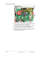
2. Connect the probes as shown in
Illustration 16.5.
3. Slowly increase voltage; observe the oscilloscope and the
current consumption during the process.
4. Check the graph and compare with possible graphs as
indicated in
Illustrations 16.2.1 - 3.
If graph and phase are as indicated in
Illustration
.
16.2.1.,
no modification is necessary.
5. If there is a deviation of the graph as compared to
Illustration 16.2.1.
turn the ferrite core at the adjustment coil.
Observe the change of the phase position indicated at the
oscilloscope.
The voltage graph should show a peak of approx. 2 mm
width before the decline (
Illustration 16.2.2.
).
6. Check the generator power consumption and compare with
the values indicated in the table in
section 16.3.
In case of deviation see instructions given in
section 16.2.
7. Secure the ferrite core after adjustment with silicone etc.
Perfect adjustment
•
The transistors do not heat up (one or both).
•
There are waves on the surface of the bath.
•
There are no streamers on the tank floor.
•
The ultrasonic noise is uniform and not shrill.
•
The performance changes only little when a beaker, etc. is
immersed in the tank.
The phases remain stable.
Summary of Contents for LC130H
Page 2: ......