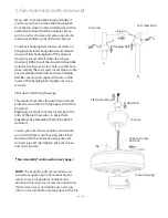
Ellington Elevating Style ELN42ABZ5 Installation Manual Download Page 8

page 7

9. Blade Assembly.

Time Saver

: Washers for blade screws can be set 

on each blade screw prior to installing blades.

Locate 15 blade attachment screws and washers 
in hardware pack. Hold blade arm up to blade 
and align holes. Insert 3 blade attachment screws 
(along with washers) with fingers first and then 
tighten screws securely with a Phillips 
screwdriver. Repeat for the remaining blades.

Remove blade arm screws and lock washers from 
fan motor and set aside.  Then, if applicable, 
remove plastic motor locks and discard. Align 
blade arm holes with motor screw holes and 
attach blade arm with lock washers and blade 
arm screws. Before securing screws permanently, 
repeat this procedure with remaining blade 
arms. Secure all screws.

Note

: Tighten blade arm screws twice a year. 

motor housing

blade arm

blade

blade arm

screws

lock washers

blade attachment

screws and washers

plastic
motor
lock

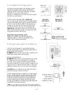
10. Testing Your Fan.

pull chain
extension

reverse

switch

It is recommended that you test fan before finalizing 
installation. Restore power from circuit box and light 
switch (if applicable). Test fan speeds with the pull 
chain located on the switch housing. Start at the OFF 
position (no blade movement). First pull will set the 
fan to HI. Second pull will set the fan to MEDIUM. 
Third pull will set the fan to LOW. Fourth pull will 
again will set the fan to OFF setting. If fan does not 
function, please refer to "Troubleshooting" section to 
solve any issues before contacting Customer Service.

Turn fan completely off 

before

 moving the reverse 

switch. Set reverse switch to recirculate air depending 
on the season:
 

- UP position in summer (

diagram 1

)


- DOWN position in winter (

diagram 2

)

A ceiling fan will allow you to raise your thermostat 
setting in summer and lower your thermostat setting 
in winter without feeling a difference in your comfort.

Important

: Reverse switch must be set either 

completely UP

 or 

completely DOWN

 for fan to 

function. If the reverse switch is set in the 

middle


position (

diagram 3

), fan will not operate.

Pull chain extension supplied or custom pull chain 
extension (sold separately) may be attached to the 
end of the pull chain.  

diagram 1

diagram 2

diagram 3

Summary of Contents for Elevating Style ELN42ABZ5

Page 1: ...Bracket Installation pg 3 Fan Assembly pgs 4 5 Wiring pg 6 Canopy Assembly pg 6 Blade Assembly pg 7 Testing Your Fan pg 7 Light Kit Assembly Optional pg 8 Troubleshooting pg 9 Parts Replacement pg 9...

Page 2: ...e to connect to the two fan lead wires consult an electrician for the proper size wire connectors to use 5 Electrical diagrams are for reference only Light kits that are not packed with the fan must b...

Page 3: ...inserts should this fan need to be returned for repairs Check against parts inventory that all parts have been included 2 Parts Inventory a canopy 1 piece b hanging bracket 1 piece c 4in downrod and h...

Page 4: ...original outlet box If installing on a vaulted ceiling face opening of hanging bracket towards high point of ceiling Arrange electrical wiring around the back of the hanging bracket and away from the...

Page 5: ...g ball Be sure stop pin aligns with slots on the inside of the hanging ball Tighten set screw securely Slide downrod through canopy Thread electrical wires through downrod and pull extra wire slack fr...

Page 6: ...ice that 3 holes are larger than the others If there are only 3 screws in top of motor housing please proceed to next paragraph If there are 6 screws in top of motor housing remove every other screw a...

Page 7: ...those referred to below please use a qualified electrician When downrod is secured in place on the hanging bracket electrical wiring can be made as follows Connect BLACK wire from fan to BLACK wire f...

Page 8: ...fan before finalizing installation Restore power from circuit box and light switch if applicable Test fan speeds with the pull chain located on the switch housing Start at the OFF position no blade mo...

Page 9: ...her and hex nut that were previously removed Refer to diagram b Tighten hex nut over lock washer for a secure fit Connect WHITE wire from light kit fitter to WHITE wire from switch housing Connect BLA...

Page 10: ...to time or exposure to salt air is specifically exempted under this warranty Neither Litex Industries nor the manufacturer will assume any liability resulting from improper installation or use of this...

Reviews: