T 3000 - T 3500
23
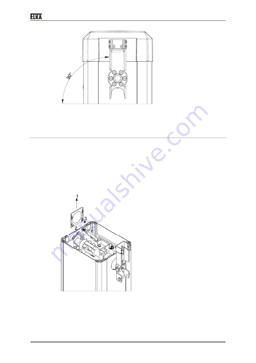
Drawing 11
4. Now retighten the four screws (M12x30 ISO 4762) at the clamping piece
with 120Nm.
7.5.1
Installation – Boom connector left side
The barrier models T 3000 – T 3500 are prepared at the factory to mount the
boom on the right side. At the left side a cap is mounted to cover the main
shaft opening.
Converting from barrier boom right to barrier boom left:
1. Remove the barrier hood.
2. Detach the cover cap at the left housing side as described in the following
drawing. First pull the spring sheet upwards (1), then turn the cover cap
approx. 60° (2) and pull it upwards (3).
Drawing 12
3. Disconnect the boom connector from the right side, if already mounted.
Connect it to the left side.
4. Mount the cover cap and the spring sheet at the right housing side.
Summary of Contents for T 3000
Page 12: ...T 3000 T 3500 11 4 Declaration of incorporation Drawing 2...
Page 18: ...T 3000 T 3500 17 7 2 Mounting dimensions Drawing 3...
Page 34: ...T 3000 T 3500 33 8 4 Circuit diagram Drawing 21...
Page 35: ...T 3000 T 3500 34 Drawing 22...
Page 36: ...T 3000 T 3500 35 Drawing 23...
Page 37: ...T 3000 T 3500 36 Drawing 24...
Page 38: ...T 3000 T 3500 37 Drawing 25...
Page 39: ...T 3000 T 3500 38 Drawing 26...
Page 40: ...T 3000 T 3500 39 Drawing 27...
Page 42: ...T 3000 T 3500 41 10 Layout exploded drawing Drawing 28...


