Page 3
M1XSP Supplementary Instructions and Release Notes
VERY IMPORTANT!
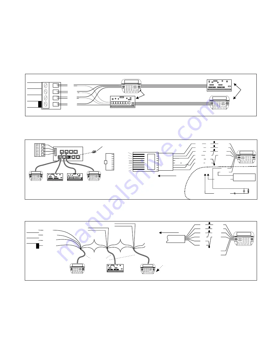
The control uses a RS-485 “differential” data bus operating at 38,400 bits per second. This is relatively high speed by industry standards
and ensures fast, accurate communications. EOL data bus terminating resistors are strongly suggested to eliminate the possibility of
reflection errors due to varying cable lengths. Every device; keypad, expander, etc. and the control has a built-in bus terminating resistor
(120 Ohm) which can be activated via a 2 pin jumper (2 Gold Pins). Two black shorting caps are included in the hardware pack. When one
of the shorting caps is placed on the two gold pins, it activates the 120 Ohm terminating resistor across Data Lines A & B. Terminating
resistors are marked JP2 on the keypads and JP1 on the expanders. From the factory, no terminating resistors are installed (activated).
WARNING! The RS-485 Data Bus must NEVER have more than 2 terminating resistors header/jumpers installed.
The M1 should have no more than 2 home run cables but devices can be daisy chained along each. The last device on each home run
SHOULD be terminated via the gold 2 pin terminating header/jumper. Placing a shorting cap on the pins will engage a 120 Ohm resistor across
data lines A & B. If there is only 1 data bus home run cable then place shorting cap on JP3 of Main Board. See other hookups below.
The optional ELK-M1DBH † Data Bus Hub is suggested if the job must have more than 2 home runs. The M1DBH accepts CAT5 or CAT6 cable
with RJ45 plugs. It keeps wires more organized while also providing easy bus termination. Essentially, the M1DBH circuit board daisy chains
the devices by series connecting the DATA lines A & B. An plug-in RJ45 terminator is supplied for use in the first unused jack.
Another option for wiring multiple home runs is with 6 conductor cable. This allows devices to daisy chained by making an in and out
connection, basically a 3 way splice of the data A (Green)wire to 2 wires of the 6 conductor cable (designated A and A1). Do the same for the
data B (White) wire. At the control splice the A1 and B1 wires to the A and B wires going to the next device. Terminate the last wired device
and the control JP3 ONLY! The data wires will be in series, but the POS (+) and Neg (-) power wires should be parallel wired to the +VKP and
Neg terminals or to an auxiliary Power Supply if the combined current draw exceeds the rated current available from the Control.
BLACK
WHITE
GREEN
RS-485 Data Bus
(Max. length is 4000 ft.
Max. bus devices vary by control.)
RED
Jumper
Terminate
these two
devices.
DO NOT Jumper
Terminate these devices.
Keypad 1
Data Bus Devices e.g. Keypads, Expanders
Keypad 3
Daisy Chain Connection of Data Bus Devices Using Two (2) Home Run Cables
+VKP
DATA B
DATA A
NEG
RS-485 DATA BUS
Install Teminating
Jumper on this last
device AND on the
control JP3.
6 conductor cable
DATA
A1 A
B1 B
DATA
A1 A
B1 B
Optional Output and Zone Input - See Keypad Instructions
Connect each device to the 6 conductor cable as shown above
Daisy Chain Connection of Data Bus Devices Using 6 Conductor Cables
Keypad
RS-485 DATA BUS
+VKP
DATA B
DATA A
NEG
Keypad
RED
GREEN
BLACK
WHITE
To 12VDC
To 12VDC
BLUE
BROWN
6 Wire
Cable
Keypad
RED +12
+
BLACK (-)
-
GREEN
WHITE
A
A1
B
B1
TO CONTROL
Keypad
ELK-M1DBH Data Bus Hub
†
Mount M1DBH inside control. Connect it to the M1
Data Bus terminals using a 4 conductor cable.
J2
J4
J6
J8
J1
J3
J5
J7
J9
RJ45 Terminating Plug Insert in first unused jack and terminate the
control at JP3. DO NOT TERMINATE AT ANY OF THE DEVICES!
CAT5 Cables
Daisy Chain Connection using the ELK-M1DBH and CAT5 Cables.
RS-485 DATA BUS
Keypad
Refer to
Keypad
Instructions
for more info
about Output
and Zone Input
+
-
A
A1
B
B1
TO CONTROL
8 - Brown
7 - Wht/Brn
6 - Orange
5 - Wht/Blue
4 - Blue
3 - Wht/Org
2 - Green
1 - Wht/Grn
Pin1
RJ45 Plug
Blue pair
is unused
COLOR CODE
for CAT5 or CAT6 Data Bus Cable
to RJ45 Plugs for ELK-M1DBH Data Bus Hub.
Pin1
F
ront
vi
e
w
Optional programmable Zone Input
Optional programmable Output
-
+
N.C.
N.O.
2200
Ohm
EOL
To BLACK (Neg)
To BLACK (Neg)
Wht/Blue
Brown
Wht/Brn
Orange
Wht/Org
Green
Blue
Wht/Grn
RED +12V
BLACK (-)
GREEN
WHITE
BROWN
BLUE
Keypad
CAT5
or
CAT6
Cable
To
+ 12V
Load (50mA max)
I.E. LED, Relay
+ VKP
DATA A
DATA B
NEG
ELK-M1 Data Bus E.O.L. Termination


