


- 48 -
Design and Functions
t
|
|
|
|
|
|
|
|
|
|
|
|
|
|
|
|
|
|
|
|
|
|
|
|
|
|
|
t
|
|
|
|
|
|
|
|
|
|
|
|
|
|
|
|
|
|
|
|
|
|
|
|
|
|
|
t
|
|
|
|
|
|
|
|
|
|
|
|
|
|
|
|
|
|
|
|
|
|
|
|
|
|
|
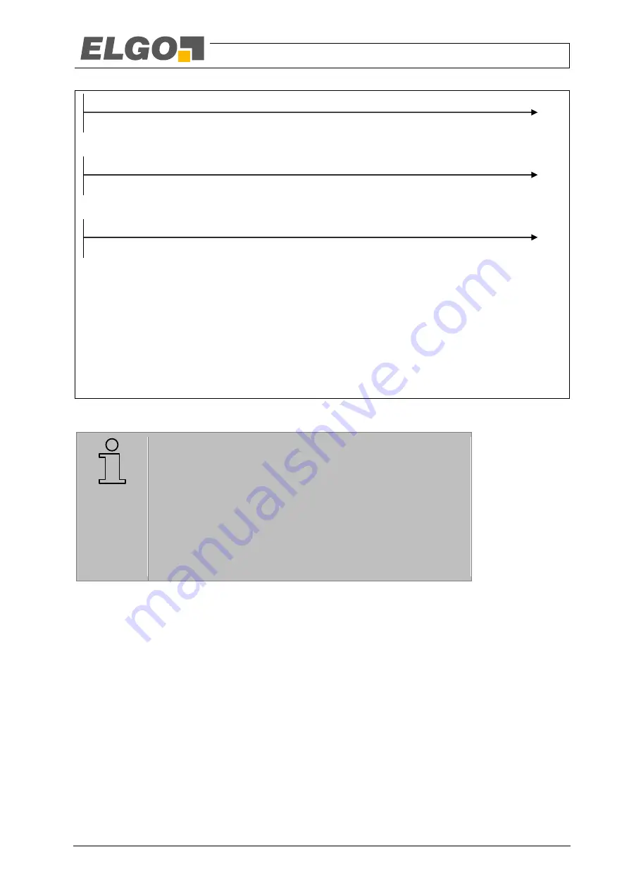
Valid position data
Request for safe state by channel A (position 0)
Request for safe state by channel B (inverted CRC check sum)
Request for safe state by both channels (position 0 and inverted CRC check sum)
Error occurs, request for safe state is sent immediately after detection.
If the error is present for a certain amount of time, the request for transition into safe state is transmitted
with every message.
Error detection channel B
Channel A signals error with the next message
Fig. 26: Example of a request of the evaluation unit for transition into safe state. Temporary signalling (top), transition from
temporary to permanent signalling (centre), and staggered signalling of the two channels (bottom).
NOTE!
The gradual request for transition into safe state allows the evaluation
unit to react more smoothly in case of a temporary interference which
may be the result of a temporary, very strong electromagnetic interfer-
ence. For example, the evaluation unit can close the safety circuit au-
tonomously after a temporary interference has disappeared, while it
makes sense to set an error in case of a persisting interference.
The described behaviour is just an example. The actual behaviour de-
pends on the evaluation unit and has to be defined and evaluated
during its development.
Further information:
Requirements for evaluation unit:
Non-severe interference:
9.5.4.1.10
Bus Timing
LIMAX44 RED divides the transmitted messages into two packets. The first data packet, consisting of segments A
to C (
9.5.4.1.2 Structure of a Message), is sent by channel A; the second data packet, consisting of segments
D to F, is transmitted by channel B. After the end of this transmission the evaluation unit has time to put the floor
information to the bus byte wise. Since the sensor is not directly ready to receive data after release of the RS-485
bus, it is imperative that the time t
P
(see Fig. 27 and Table 8) is allowed to elapse before the evaluation unit puts
data on the bus.
The interface parameters for the structure of the symbols are described in
When changing from dual-channel operation to single-channel operation and back, the message-sending-
interval is shortened/lengthened by the time t
C
once because there are no internal comparisons in single-
channel operation.


