Elgar CW-M Series
5
OPERATION....................................................................33
5.1
Parallel and Multiphase Operation ........................................................... 35
5.2
Remote Control Signals ........................................................................... 36
6
MAINTENANCE...............................................................37
6.1
Periodic Service ....................................................................................... 37
6.2
Fuse Replacement ................................................................................... 37
LIST OF FIGURES
Figure 1–1 ContinuousWave (Model CW1251M) Front Panel........................................1
Figure 3–1 Slide Mounting............................................................................................13
Figure 3–2 Mounting Dimensions, Front and Rear Views (CW 801M, CW 1251M) .....14
Figure 3–3 Mounting Dimensions, Front and Rear Views (CW 2501M) .......................15
Figure 3–4 Mounting Dimensions, Top and Side Views (CW 801M, CW 1251M) .......16
Figure 3–5 Mounting Dimensions, Top and Side Views (CW 2501M) .........................17
Figure 3–6 Input Power Connections ...........................................................................18
Figure 3–7 Output Power Connections.........................................................................20
Figure 3–8 Output Voltage Sensing Configuration .......................................................21
Figure 3–9 Sense Connections ....................................................................................22
Figure 4–1 CW Rear Panel ..........................................................................................25
Figure 5–1 CW Front Panel Controls............................................................................33
Figure 5–2 External Control Connector ........................................................................36
LIST OF TABLES
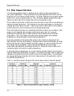
Table 3–1 Recommended Wire Gauge Selection Guide ..............................................10
Table 3–2 Recommended Cables ................................................................................19
Table 4–1 CONFIG Dipswitch Functions......................................................................26
Table 4–2 Phase Angles ..............................................................................................31
Table 6–1 Replacement Fuses.....................................................................................37
vi
Summary of Contents for CW 1251M
Page 2: ......
Page 3: ......
Page 4: ......
Page 6: ...ii This page intentionally left blank...
Page 12: ...Elgar CW M Series This page intentionally left blank 2...
Page 24: ...Elgar CW M Series Figure 3 2 Mounting Dimensions Front and Rear Views CW 801M CW 1251M 14...
Page 25: ...Elgar CW M Series Figure 3 3 Mounting Dimensions Front and Rear Views CW 2501M 15...
Page 26: ...Elgar CW M Series Figure 3 4 Mounting Dimensions Top and Side Views CW 801M CW 1251M 16...
Page 27: ...Elgar CW M Series Figure 3 5 Mounting Dimensions Top and Side Views CW 2501M 17...
Page 34: ...Elgar CW M Series This page intentionally left blank 24...
Page 38: ...Elgar CW M Series 4 3 2 Setup for Six in Parallel Configuration 28...
Page 39: ...Elgar CW M Series 4 3 3 Setup for Six Phase Configuration 29...
Page 40: ...Elgar CW M Series 4 3 4 Setup for Two Phase Configuration 30...
Page 42: ...Elgar CW M Series This page intentionally left blank 32...
Page 48: ...Elgar CW M Series This page intentionally left blank 38...


