-7-
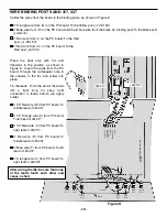
Install binding posts 1-7 with the colors in order, as shown in Figure D. Insert the post into the hole and fasten
it with the nut and lockwasher. Tighten down the nut with pliers.
Cut off the tabs on the two potentiometers and install them with the lugs up, as shown in Figure D. Secure
in place with a 5/16” lockwasher, 8mm flat washer and 7mm nut.
Turn both potentiometer shafts all the way counter-clockwise. Line up the line on the
knobs with the first line on the voltage scale. Press knobs onto the shaft of the
potentiometers.
Note the lug configuration on the rocker switch. Push the switch into the hole in the
chassis with lug 1 on top as shown in Figure D.
PANEL ASSEMBLY
Figure D
Lug 1
Lockwasher
Nut
Black
Red
Black
Yellow
Rocker Switch
Rear View of Rocker Switch
7mm Nuts
8mm Washers
5/16” Lockwashers
Potentiometers
* Cut off tabs
Red
Yellow
Yellow
IN
C
RE
A
SE
1
2
3
4
5
6
7
1
2
3


