esca User’s Manual v1.2
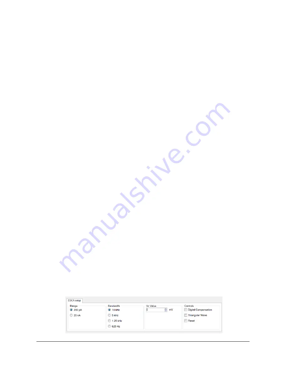
The upper section of the GUI presents the ESCA device specific commands (see the
“ESCA Setup” section for details).
Just below you can find some estimated statistic values on the input signal (see the
“Statistic Data” section for details), while on the right there are the controls to associate
an oscilloscope-like trace (beam) with a specific input signal in the visualization
window (in the case of ESCA devices, there is only one input channel available). See
the “Trace Visualization” section for details.
On the right there is an estimation of the input bitrate.
In the bottom you can find, in addition to the “Open Config” button already described
in the previous section, the following buttons:
Connect
– Starts the communication with the ESCA hardware.
Show
– Displays the data visualization window.
Save
– Save data.
In the bottom-right corner there is a drop-down list of the serial numbers of all the
recognized ESCA devices connected to the PC.
NOTE: Multiple instances of the software can run on the same PC enabling to control
several ESCA devices connected to the same PC. If more than one ESCA device are
connected, you must first choose the correct device Serial Number to be controlled.
To start acquiring data, click on the “
Connect
” button.
ESCA
S
ETUP
The ESCA setup tab contains the following controls:
Range
Bandwidth
Constant Control Voltage
Digital Compensation
Triangular Control Voltage
ESCA reset


