23
VENTING
Element4 Gas Fireplaces
European
Home
.com
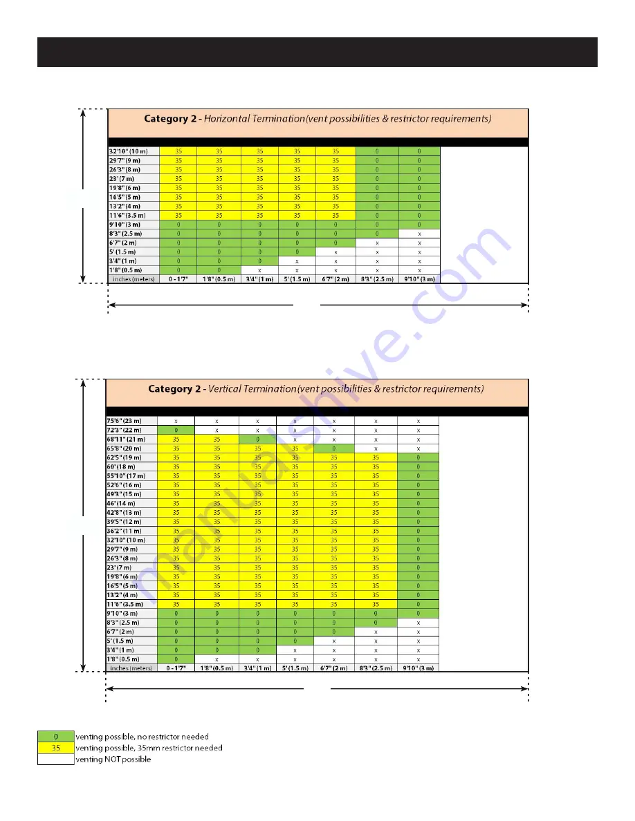
VENTING CHARTS
HORIZONTAL TERMINATIONS & RESTRICTOR USE
rise
run
VERTICAL TERMINATIONS & RESTRICTOR USE
KEY
x
Page 1: ...appliance Do not touch any electrical switch do not use any phone in your building Leave the building immediately Immediately call your gas supplier from a neighbor s phone Follow the gas supplier s...
Page 2: ...Electric 19 Venting 20 Configuration 20 Venting Charts 23 Venting Clearances 24 Enclosing the Fireplace 26 Non Combustible Materials List 26 Rough Opening Dimensions 29 Convection Air Opening 32 Cold...
Page 3: ...ONGLY RECOMMEND that you install in front of the fireplace a fire screen or to protect young toddlers a hearth gate HOT SURFACES Be aware that although safe some combustible materials and finishes eve...
Page 4: ...upplier Any alteration to the product that causes soot or carbon to form and results in damage is not the responsibility of the manufacturer ONLY a qualified person may open the door remove the glass...
Page 5: ...ed by the manufacturer NO SUBSTITUTE panels shall be used DO NOT USE abrasive cleaners on the panels DO NOT ATTEMPT to clean the glass panels when they are hot TURN OFF the gas before servicing the ap...
Page 6: ...wallboard that is specified in the manual may be used when enclosing the fireplace The venting MUST follow the model specific graph shown in the manual A restrictor may or may not need to be used base...
Page 7: ...m air This design therefore requires the use of non combustible wall materials and gives you beauty for your effort When the air within the chase is warmed by the fireplace it rises and exits through...
Page 8: ...Maximum in w c 4 0 10 8 kpa 0 99 2 68 Manifold Pressure Minimum in w c 0 4 1 5 kpa 0 1 0 38 Main Burner Injector Marking 650 x2 220 x2 Pilot Injector Marking 31 2 27 1 Efficiency 82 1 AC Adapter Conn...
Page 9: ...VIDER MKII LUCIUS 140 ROOM DIVIDER MKII A DWG file is available for download at www europeanhome com for design specific dimensions not listed Letter Inches Millimeters A 603 8 1532 B 545 8 1386 C 165...
Page 10: ...ile is available for download at www europeanhome com for design specific dimensions not listed LUCIUS 140 TUNNEL MKII LUCIUS 140 TUNNEL MKII Letter Inches Millimeters A 605 8 1541 B 5315 16 1369 C 16...
Page 11: ...vailable for download at www europeanhome com for design specific dimensions not listed LUCIUS 140 1 3 MKII LUCIUS 140 1 3 MKII Letter Inches Millimeters A 545 8 1386 B 145 16 363 C 115 16 288 D 111 2...
Page 12: ...ble for download at www europeanhome com for design specific dimensions not listed LUCIUS 140 2 3 MKII LUCIUS 140 2 3 MKII Letter Inches Millimeters A 165 8 422 B 545 8 1386 C 145 16 363 D 115 16 288...
Page 13: ...place to be levelled Hearth Panel supports various Fire Media Primary Burner produces the flame Flange Pilot Burner the part of the safety circuit which lights the Main Burner 2nd Thermocouple the par...
Page 14: ...y Burner produces the flame Flange Pilot Burner the part of the safety circuit which lights the Main Burner 2nd Thermocouple the part of the safety circuit which monitors the Main Burner Finish Trim h...
Page 15: ...100 mm to the bottom Any spacer or framing used closer than this dimension must be non combustible e g metal The minimum distance from the bottom of the appliance to the room ceiling is 72 1830 mm Wh...
Page 16: ...rials may be installed to a zero clearance to the outer faces of the appliance outer frame face However they must not cover or prevent the removal of the glass panels or other fireplace parts Below th...
Page 17: ...ccordance with the chart below Mantels made of non combustible material are allowed inside these dimensions but they will be subjected to elevated temperatures and may become too hot to touch A typica...
Page 18: ...ment of air and must not allow excessive convection air to build up within the chase The top of the outlet s must be at least 1 25 mm down from the room ceiling The top of the outlet s must be no more...
Page 19: ...plumber or gasfitter The gas control inlet accepts a 3 8 NPT fitting This fireplace is shipped from the factory for use with natural gas See appendix for LP propane conversion instructions Schedule 4...
Page 20: ...al vent pipe surface a minimum clearance of 1 25 mm must be maintained between combustible materials and any other vent pipe surface The horizontal parts of the venting must be pitched up away from th...
Page 21: ...Q Horizontal Pipe Section T Vertical Pipe Section S CALCULATING THE TOTAL VERTICAL SECTION TVS Calculate the Total Vertical Section by adding up all vertical upward sections in your specific vent desi...
Page 22: ...l to horizontal For each 90 elbow in the horizontal section you must add 80 2m to your THS For each 45 elbow in the horizontal section you must add 40 1m to your THS INTERPRETING THE GRAPH RESULTS Onc...
Page 23: ...23 VENTING Element4 Gas Fireplaces EuropeanHome com VENTING CHARTS HORIZONTAL TERMINATIONS RESTRICTOR USE rise run VERTICAL TERMINATIONS RESTRICTOR USE rise run KEY x...
Page 24: ...24 VENTING Element4 Gas Fireplaces EuropeanHome com HORIZONTAL VENT TERMINATION CLEARANCES AND REQUIREMENTS CLEARANCES...
Page 25: ...and do not supersede local codes in any way Install venting according to local codes these instructions the current National Fuel Gas Code ANSI Z223 1 in the USA or the current standard of CAN CSA B14...
Page 26: ...are considered non combustible The table below shows a list of materials which as of this writing are reported by their manufacturers to be non combustible in accordance with the ASTM E136 standard AN...
Page 27: ...s 4 The controls will be mounted to your enclosure and below the burner The controls are at the end of a 50 1270 mm line set and are to be mounted to the Wall Access Door which is included The control...
Page 28: ...Gap MUST BE MAINTAINED Shield Over Finished Wall Shield Over Finished Wall Combustible Wall Combustible Wall Combustible Wall Combustible Wall Shield Over Finished Wall Shield Over Finished Wall 2 50...
Page 29: ...off frame face in line with the front inside blue limit and centered left and right above This minimum area MUST BE DEFINED BY NON COMBUSTIBLE MATERIAL The inside of the enclosing walls including any...
Page 30: ...face in line with the front inside blue limit and centered left and right above This minimum area MUST BE DEFINED BY NON COMBUSTIBLE MATERIAL The inside of the enclosing walls including any necessary...
Page 31: ...ne with the front inside blue limit and centered left and right above This minimum area MUSTBEDEFINEDBYNON COMBUSTIBLEMATERIAL The inside of the enclosing walls including any necessary framing may be...
Page 32: ...off frame face in line with the front inside blue limit and centered left and right above This minimum area MUSTBEDEFINEDBYNON COMBUSTIBLEMATERIAL The inside of the enclosing walls including any neces...
Page 33: ...inish For example a thinner wall product and a layer of stone may be thick enough to reach the trim edge If a painted finish is desired then a wall at least 1 2 12 mm thick will suffice Minimum Wall T...
Page 34: ...uropeanHome com Convection Air Outlet Area by Model Model Square Inches Square Centimeters Lucius 140 RD MKII 70 452 Lucius 140 T MKII 70 452 Lucius 140 1 3 MKII 70 452 Lucius 140 2 3 MKII 70 452 Baff...
Page 35: ...hout the installation Any support framing NON combustible framing ONLY must be at least 2 50 mm away above and beside the fireplace The entire weight of the non combustible walls must be borne by a st...
Page 36: ...Wall Access Door is provided with your fireplace and is designed to hold the receiver and gas control When locating the Wall Access Door you must consider four types of access 1 Air access Room air mu...
Page 37: ...white door frame cover onto the frame and secure it with the four bolts Fit the gas control tab into the bracket on the Access Door frame Tighten the bolt through the mounting bosses Carefully cut th...
Page 38: ...ds 2 Start the fireplace with the hearth panel in place and with all of the glass panels fixed correctly in place Ensure that the main burner flames engulf the 2nd thermocouple and the fireplace stays...
Page 39: ...in the pilot shield Scatter the bag of chips evenly on the hearth panel and burners Ensure that the area inside the pilot shield and the area around the 2nd thermocouple remains clear of media With th...
Page 40: ...t none of the stones glass enters the pilot area or restricts the operation of the 2nd thermocouple The arrangement is now complete However it is important to check that the pilot flame is still visib...
Page 41: ...6 Magnets 18 Long Screen 2 Short Screen 1 LUCIUS 140 RD MKII Upper Tabs 6 Lower Tabs 6 Magnets 18 Long Screen 2 Short Screen 1 Place the 2 Lower Tabs on the trim with the short side against the glass...
Page 42: ...n will look like when it is attached correctly to the top Upper Tabs view from inside of the standoff frame Place the 2 Upper Tabs on the inside of the top stand off frame One magnet will be hidden at...
Page 43: ...is is what the screen will look like when it is attached correctly to the top Lower Tabs view between the screen and the glass The screen is installed properly in the photo above Please make sure that...
Page 44: ...the remote and receiver 8 Follow USING THE REMOTE CONTROL ELECTRONIC IGNITION SEQUENCE to setup and use remote PAIRING THE REMOTE AND RECEIVER System Reset From the factory the remote control will com...
Page 45: ...es press or button 7 To confirm press and buttons simultaneously or wait CHILD PROOF 1 2 ON AM PM OFF ON To activate press and buttons simultaneously displayed and the remote is rendered inoperable ex...
Page 46: ...the main valve knob to OFF and follow the operating instructions TURN OFF GAS TO APPLIANCE STANDBY MODE PILOT FLAME Remote Press and hold button to set appliance to pilot flame TO TURN OFF FIRE 1 2 ON...
Page 47: ...to choose between 6 To confirm press button MODES of OPERATION 1 2 ON AM PM OFF Thermostatic Mode The room temperature is measured and compared to the set temperature The flame height is then automat...
Page 48: ...To activate a function press the relevant button and hold for 10 sec 3 The function icon will continue to flash until activation is complete Activation is complete when the function icon is displayed...
Page 49: ...ass is cold some condensation may appear on the glass after lighting the fireplace This is normal and the condensation will disappear as the glass warms During this first fire examine the flame for ap...
Page 50: ...f the retaining bolts and clamps holding in the first piece of glass REMOVING THE GLASS No 2 Phillips screwdriver not included Gloves not included Suction Cup TOOLS REQUIRED The glass panels on this f...
Page 51: ...are tight and square to each another tighten the retaining bolt s on each clamp NO MORE THAN 1 2 TURN past finger tight PROPERLY PLACE CLAMP AND SEAL THE GLASS PANEL S BEFORE LIGHTING THE FIRE Standof...
Page 52: ...eplace any part of the control system and any gas valve that has been under water Any alteration to the product that causes soot or carbon to form and results in damage is not the responsibility of th...
Page 53: ...have appeared these must be immediately replaced 3 Ensure that there is no foreign material in the vents Survey by removing the cap and shining a light down the vent 4 Check all joints and pipes to ma...
Page 54: ...becomes the property of European Home All warranty claims must be submitted through the dealer from which you purchased the product Check with your dealer in advance for any costs to you when arrangin...
Page 55: ...ed heating appliance or equipment The sign shall read in print size no less than one half 1 2 inch in size GAS VENT DIRECTLY BELOW KEEP CLEAR OF ALL OBSTRUCTIONS 4 INSPECTION The state or local gas in...
Page 56: ...56 Element4 Gas Fireplaces EuropeanHome com APPENDIX TWO...
Page 57: ...not connected Confirm integrity of 2nd thermocouple and connection No No No Yes C Spark will occur each second Ignition components not operating properly Check connection between ignition cable and i...
Page 58: ...e label on the receiver Do not coil the ignition cable Element4 140 models ONLY Pilot flame under hearth panel not establishing Remove hearth panel and glass and check for proper pilot operation If pi...
Page 59: ...e fire will continue to function normally The valve will turn to pilot flame if the set temperature and the ambient temperature remain the same over a 6 hour period No Main burner remains lit while fl...
Page 60: ...instructions Flow of fresh air and or exhaust is blocked Ensure that vent configuration is within the vent chart requirements Check termination for blockage and or appropriate type No J Flames become...
Page 61: ...n screw the wall switchplate to the workbox with the two screws provided and attach the faceplate included A B Figure 5 1 Figure 5 2 USING THE WALL SWITCH see Figure 5 2 Note that with the wall switch...
Page 62: ...s need to be closed for 12 seconds to turn the motor from one end stop to the other end stop To set the valve to the Off position close contacts 1 2 and 3 simultaneously for 1 second Modes of operatio...
Page 63: ...ion 53 M MAINTENANCE Burner 52 Pilot 52 Thermocouples 53 Vent 53 MANTELS 17 N NON COMBUSTIBLE MATERIALS Minimum Clearances 16 O OPERATING THE FIREPLACE Test Fire 38 Using the Remote Control 44 Using t...
Page 64: ...ireplaces EuropeanHome com Rev B IGE411II 160801 EUROPEAN HOME a division of Europa Ja Inc 30 Log Bridge Road Building 300 Suite 303 Middleton MA 01949 www europeanhome com Imported and distributed in...