background image

18

H

COMMISSIONING

H1

Preliminary checks, adjustments and 
operational tests

H1.1

Electrical and plumbing checks

Before starting the machine, it is necessary to:

check the correct connection of the electrical wires
powering the machine;

make sure the power supply voltage and frequency
match the data given in Table 1;

check the correct connection of the water supply
and discharge pipes (par. Figure 8 “Unpacking”);

make sure all the guard and safety devices are in
place and efficient.

H1.2

Tank components positioning check

H1.2.1

Fitting of filters and overflow check

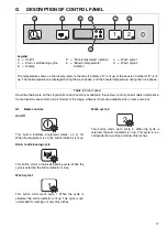
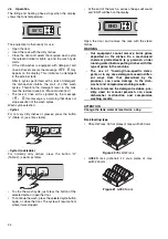
Make sure the tank filter “1”, overflow “2” (Figure 14)
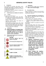
and flat filters “3” are correctly fitted (Figure 15).

Figure 14 Tank filter and overflow

Figure 15 Flat filters

H1.2.2

Arm fitting check

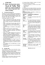
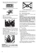
Make sure the upper and lower wash and rinse arms
are correctly fitted (Figure 16).

Figure 16 Wash arms

H2

Commissioning

Turn on the water supply tap.

Activate the main switch ahead of the machine by
turning it to “I”.

Press the On/Off button (“A” - Table 2 “Control
panel”).

H3

Detergent/rinse aid dispensers and 
prearrangements

If the machine is connected to a water softener and/or
a reverse osmosis system, contact the detergent sup-
plier for a specific product. 

If the peristaltic dispensers are installed in the
machine, the dosage of detergent/rinse aid is done
automatically according to the desired concentration.
The concentration of detergent/rinse aid depends on
the type of product used and the hardness of the sup-
ply water (check the characteristics on the product
label).

ATTENTION
The peristaltic dispensers (detergent and rinse aid)
and the tube inside the rinse aid dispenser require
periodical maintenance (at least once or twice a
year) or after prolonged machine idle periods.

ATTENTION!

These operations must only
be carried out by specialized
technicians provided with
adequate personal protection
equipment (e.g. safety foot-
wear, gloves, glasses, etc.),
tools and ancillary means.

ATTENTION!

The following operations must
be carried out by operators pro-
vided with suitable personal
protection equipment (e.g. pro-
tective gloves, etc.) and with the
machine switched off and cold.

1

2

3

3

Summary of Contents for NUC1DDRUKP

Page 1: ...ge 9 D1 Main technical characteristics Page 9 D2 Power supply characteristics Page 9 E TRANSPORT HANDLING AND STORAGE Page 11 E1 Introduction Page 11 E1 1 Transport Instructions for the carrier Page 11 E2 Handling Page 11 E2 1 Procedures for handling operations Page 11 E2 2 Shifting Page 11 E2 3 Placing the load Page 11 E2 2 Shifting Page 11 F INSTALLATION AND ASSEMBLY Page 12 F1 Customer responsi...

Page 2: ...rds Page 21 I1 2 Safety signs to be placed on the machine or near the work area Page 21 I2 Decommissioning Page 21 I3 Instructions regarding use and maintenance Page 21 I4 Foreseeable improper use Page 22 I5 Residual risks Page 22 J NORMAL MACHINE USE Page 23 J1 Foreseen use Page 23 J2 Characteristics of personnel enabled to operate on the machine Page 23 J3 First use Page 23 J4 Daily activation o...

Page 3: ...nstallation diagram Page 15 Figure 14 Tank filter and overflow Page 18 Figure 16 Wash arms Page 18 Figure 17 Dispenser prearrangement Page 19 Figure 18 Detergent dispenser terminal board Page 19 Figure 19 Rinse aid dispenser terminal board Page 19 Figure 20 YELLOW rack Page 24 Figure 21 GREEN rack Page 24 Figure 22 BLUE rack Page 25 Figure 23 YELLOW container Page 25 Figure 24 Overflow removal Pag...

Page 4: ...here the machine is used so that it is always at hand for consultation in case of doubts or whenever required If after reading this manual there are still doubts regarding machine use do not hesitate to contact the Manufac turer or the authorized after sales service centre to receive prompt and precise assistance for better operation and maximum efficiency of the machine During all stages of machi...

Page 5: ...mbina tion with a guard Customer the person who purchased the machine and or who manages and uses it e g company entrepreneur firm Emergency stop device a set of components intended for the emergency stop function the device is activated with a single action and prevents or reduces damage to persons machines property animals Electrocution an accidental discharge of electric current on a human body...

Page 6: ...hion and replacements using spare parts different from those specified in the spare parts catalogue the fitting and use of non original spare parts and accessories can negatively affect machine operation F Mod factory description of product Comm Model commercial description PNC production number code Ser Nr serial number AC 230V 1N power supply voltage 50 Hz power supply frequency Max 2 85 kW max ...

Page 7: ...uring the various phases of the machine s service life 1 Use heat resistant gloves suitable for contact with water and the substances used see the safety data sheet of the substances used to check other possible PPE Failure to use the personal protection equipment by operators specialized technicians or users can involve exposure to chemical risk and possible damage to health B9 Keeping the manual...

Page 8: ...in technical characteristics performance and consumption D2 Power supply characteristics The AC power supply to the machine must meet the following conditions max voltage variation 10 max frequency variation 1 continuous 2 for a short period Harmonic distorsion unbalanced three phase supply voltage voltage pulses interruption dips and the other electric characteristics must respect the provisions ...

Page 9: ... safety device is provided to disconnect the power in case of a first fault to earth an isolation controller must be provided to indicate the occurrence of a first fault by a live part to the masses or to earth This device must activate an audible and or visual signal which must continue for the duration of the fault For example in a TT system it is necessary to install a differential circuit brea...

Page 10: ... vertically in order to avoid impacts handle the machine keeping it at minimum height from the ground E2 2 Shifting The operator must have a general view of the path to be followed stop the manoeuvre in case of hazardous situa tions E2 3 Placing the load Before placing the load make sure the way is free and that the floor is flat and can take the load E3 Storage The machine and or its parts must b...

Page 11: ...tics of the place of installation The machine is designed for installation in professional and not domestic type kitchens Water collection traps metal grates must be arranged in the floor at the machine discharges see par F5 2 Installation dia gram possibly replaceable with a single water trap sized for a flow rate of at least 3 l s Figure 5 Recess dimensions If the machine is installed on a speci...

Page 12: ... safely kept recycled or burned in an appropriate waste incineration plant Recyclable plas tic components are marked as follows Parts in wood and cardboard can be disposed of respecting the current regulations in the country where the machine is used F5 Plumbing connections ATTENTION Machines marked Watermark must be installed in conformity with AS NZS 3500 1 and the non return device supplied wit...

Page 13: ... sure reducer ahead of the machine For model with drain pump place the discharge pipe D Figure 13 at a height of between 750 mm and 1000 mm measured from the support surface Subsequently check that approx 3 litres of water come out of the discharge pipe during the rinse phase F5 1 Plumbing circuits Plumbing circuit diagram undercounter type with drain pump LEGEND WI Water inlet D Drain M1 Wash pum...

Page 14: ... electrical connections Figure 13 Installation diagram Legend WI Water inlet 3 4 G D Drain outlet Discharge pipe int diameter 40 mm for model with gravity discharge 20 mm for model with drain pump EI Power supply entry XD Pipe entry for detergents EQ Equipotential screw With drain pump D D D WI WI WI XD XD EI EI EI EQ EQ With drain pump ...

Page 15: ...tric pump windings cuts off the power to the pump in case of faulty operation A device prevents the booster water from returning back into the system in the event of a water supply system fault An overflow pipe connected to the discharge ensures a constant water level in the tank The Manufacturer declines any liability if the acci dent prevention regulations are not respected ATTENTION Work on the...

Page 16: ... lit up Wash cycle 1 This button starts wash cycle 1 When the cycle is selected the button indicator is lit up This cycle is rec ommended for washing not very dirty dishes Wash cycle 2 This button starts wash cycle 2 When the cycle is selected the button indicator is lit up This cycle is rec ommended for washing normally dirty dishes Legend A On Off C Drain self cleaning cycle K Display D Tank tem...

Page 17: ...ress the On Off button A Table 2 Control panel H3 Detergent rinse aid dispensers and prearrangements If the machine is connected to a water softener and or a reverse osmosis system contact the detergent sup plier for a specific product If the peristaltic dispensers are installed in the machine the dosage of detergent rinse aid is done automatically according to the desired concentration The concen...

Page 18: ...erminal board Connect the detergent dispenser between termi nals 7 and 9 These connection points will be pow ered during tank filling and at the start of the wash cycle for the set time see par H4 Dispenser adjustment Figure 19 Rinse aid dispenser terminal board Connect the rinse aid dispenser between termi nals 8 and 9 These connection points will be pow ered during tank filling and at the end of...

Page 19: ...or for detecting the concentration in the tank a typical setting could be the dispenser is not activated during tank fill ing the dispenser is activated during wash pump operation and thanks to the concentration detected by the sensor the correct amount of deter gent is dispensed 2 Membrane rinse aid dispenser To vary the dose adjust the screw D as required Figure 17 Suggestion To check the effect...

Page 20: ...l display During maintenance several risks remain as these could not be eliminated and must be neutralised by adopting specific measures and precautions Do not carry out any checking cleaning repair or mainte nance operations on moving parts Workers must be informed of this prohibition by means of clearly visible signs To guarantee machine efficiency and correct opera tion periodical maintenance m...

Page 21: ...isks care fully indicating the personal protection equipment to be used by them Sufficient spaces are provided for during the machine installation stages in order to limit these risks To preserve these conditions corridors and areas around the machine must always be kept free of obstacles e g ladders tools contain ers boxes etc clean and dry well lit For the Customer s complete information the res...

Page 22: ... supply J3 First use Do a couple of empty cycles to clean the tank and all pipes from manufacturing process oils J4 Daily activation of the machine Make sure the filters arms and overflow are cor rectly fitted according to that indicated in par H1 2 Tank components positioning check Turn on the water supply tap Activate the main switch ahead of the machine by turning it to I Press the On Off butto...

Page 23: ...2 see times table To stop the wash cycle just press the button of the selected cycle or open the door To continue the wash press the selected cycle button again or close the door The cycle will resume from where it was stopped At the end of the wash a series of beeps will sound and END will flash on the display Open the door and remove the rack with the clean dishes WARNING Our equipment cannot re...

Page 24: ... any residuals and ensure bet ter hygiene over time Open the door and pull out the rack with the clean dishes Remove the tank filters and the overflow W Figure 24Overflow removal Close the door Select the cleaning cycle by pressing the button B Table 2 The message CLE CLEAN will be displayed throughout the cleaning cycle Code Description Cause Cure A1 LOW WATER Check if the tap is turned on Check ...

Page 25: ...TTENTION Wash the stainless steel surfaces with lukewarm soapy water absolutely avoiding the use of deter gent products containing abrasive substances steel wool steel scrapers or brushes then rinse with a wet cloth and dry thoroughly Clean the control panel with a soft cloth moistened with water and if necessary neutral detergent To reduce the emission of pollutants into the environ ment it is ad...

Page 26: ...the local dealer or agent the after sales assis tance service or the local body responsible for waste disposal J12 Troubleshooting THE DISHWASHER DOES NOT SWITCH ON 1 Make sure the socket is powered 2 Make sure the plug is properly inserted in the power socket 3 Check the fuse If necessary replace it THE DISHWASHER DOES NOT WASH PROPERLY 1 Check the suction filter and carefully clean it if dirty 2...

Reviews: