22/38
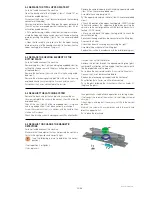
5-2 REPLACE THE TOTAL UPPER PLATE KIT
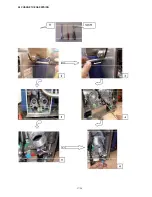
Switch off and disconnect the machine.
Open the back panel of the tilting box ( items 100 and 101 on
articulation exploded view ).
Disconnect the 3 wires (small terminal block and the Lumberg
connector of the probe).
Unscrew and remove from the tilting box the upper plate cable
(item 40 on the cover exploded view ) connector ( item 98 on
articulation exploded view ).
• Put a protection (e.g. clothes, silicon liner) on the glass surface.
• Hold the lid down with one hand and unlock the upper heating
plate by pushing the button ( item 41 on the cover exploded
view ).
• Open the lid carefully and take care that the upper heating
plate removes out of the cooking chamber (in fi nal position the
upper heating plate stands on the glass).
Remove the complet upper plate kit including upper plate cable
( item S21 on the cover exploded view ).
Assemble the new upper plate kit :
Put the upper plate cable in the hole ( item S24 cover exploded
view )
• Check the position of the upper heating plate: FRONT symbol
to front and remount the upper heating plate by pushing the
column into the central guidance until the locking mecanism is
locked ( CLICK sound).
• Move up and down the upper heating plate to check the
correct functioning.
Reconnect the upper plate cable connector on the tilting box.
Rconnect the 5 wires.
Check the correct functioning by measuring the right T°.
Assemble the back panel of the tilting box.
Replace the machine in accordance with the installation diagram.
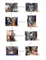
5-3 REPLACE THE HEATING ELEMENT OF THE
BOTTOM PLATE
Switch off and disconnect the machine.
Remove the glass (Item 1 on the working top exploded view) by
cutting the silicone seal with the glass cutting device (see list
of required tools).
Remove the front panel (items 28 and 30 in the housing explo-
ded view).
Remove the electromagnet support (Item 33 on the housing
exploded view) by unscrewing the 2 screws and the 2 nuts.
Disconnect the 2 wires connected to the resistor .
Unscrew the 2 nuts of the resistor.
Remove the resistor through the opened working top (glass
removed). Pay attention not to damage the other internal parts
like the probe tube and the probe!
Put in place the new resistor and fi x it in using the 2 new nuts
Connect the 2 wires disconnected before.
Replace the electromagnet support and the front panel.
Pay attention that all wires are still well connected.
Put in the glass following the instructions written in chapter 5-7
(Replace the glass).
HSPP tech GB 03 09
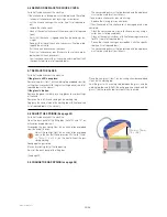
5-4 READJUST THE LATCHING SYSTEM
Remove the black cap on the handle, and unscrew the nut.
Unscrew completly the screw in the washer ( item 58 of the lid
exploded view )
Check if the seal ( item 59 of the lid exploded view ) is in place
and in a good position. If not , place correctly or change it.
Screw the screw until that is in contact with the handle, then
make a half turn back.
Check if the latching system is working correctly. Pay attention that
tha appliance has to be either in operation or in testing mode.
If not reajust the screw of the washer ( in small steps screw or
unscrew )
Check again and repeat if necessary until fi nd the correct
position.
Maintain the screw with a screw driver and in the same time
block the opposite nut.
Put in place the black cap.
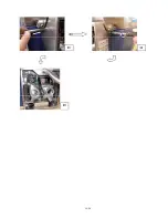
5-5 READJUST OR CHANGE THE MAGNETIC
DETECTORS
Switch off and disconnect the machine.
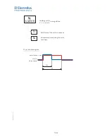
Make sure that the detector that has not passed the continuity
test is in the right position and correctly tight.
( see the following picture to determine the correct
position ).
If not: reposition it or tighten it.
If yes: replace it.
Summary of Contents for HSG Panini
Page 1: ...Service Manual GB 07 2009 HSG Panini Service manual ...
Page 2: ...2 2 50mm 50mm 7 5 190mm ...
Page 3: ......
Page 4: ......
Page 11: ...7 38 Explanation on software settings EU Version U207 ...
Page 12: ...8 38 Explanation on software settings US Version U202 U208 ...
Page 28: ...24 38 HSPP tech GB 03 09 ADJUST THE SPRINGS ...
Page 29: ...25 38 HSPP tech GB 03 09 ...
Page 30: ...26 38 ...
Page 31: ...27 38 5 9 CHANGE THE GAS SPRING ...
Page 32: ...28 38 ...
Page 33: ...29 38 ...
Page 41: ...37 38 ...
Page 43: ......
Page 49: ...Vue éclatée Couvercle Cover exploded view Explosionszeichnung Haube F HSPP FR 03 09 ...
Page 51: ...Esploso coperchio Despiece tapa Sprängskiss lock H HSPP FR 03 09 ...
Page 53: ...Vue éclatée Articulation Hinge exploded view Explosionszeichnung Gelenk J HSPP FR 06 09 ...
Page 55: ...Esploso articolazione Despiece articulación Sprängskiss Rotation L HSPP FR 06 09 ...
Page 59: ...Vue éclatée Electrique Electric exploded view Explosionszeichnung Elektrik P HSPP FR 03 09 ...
Page 61: ...Esploso elettronica Despiece electricidad Sprängskiss elektronik R HSPP FR 03 09 ...
Page 64: ......


