23/38
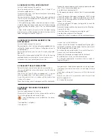
5-6 REPAIR OR REPLACE THE CHOKE COVER.
Switch off and disconnect the machine.
If the choke cover is damaged, it must be replaced. Therefore:
- take out all choke cover pins by using a screw driver.
- cut the silicone sealing with a cutter (see list of required to-
ols).
- remove the choke cover.
- clean all the contact surfaces with Acetone (see list of required
tools).
- Verify that the choke is in good condition (no bendings, da-
mages.
- Readjust the strips of the choke, if necessary. If not possible,
replace the entire lid!
- Put the new choke cover on the choke.
- Press in all choke cover pins (Make sure to use the new pins
delivered with the choke cover).
- Seal the choke cover with a silicone rod and smoothen it with
the specifi c tool (see list of required tools).
- The concerned parts must not be touched and the appliance
must not be used for at least 8hours.
If one or more choke cover pins are missing:
- Replace the missing pins by new ones.
If the silicone rod of the choke cover is damaged or no more
complete:
- Clean the concerned area from old silicone rests by using a
cutter (see list of required tools).
- Clean all the contact surfaces with Acetone or regular primer
for RTV (see list of required tools).
- Renew the silicone sealing and smoothen it with the specifi c
tool (see list of required tools).
- The concerned parts must not be touched and the appliance
must not be used for at least 8hours .
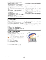
5-7 REPLACE THE GLASS
Switch off and disconnect the machine.
If the glass is still in one piece:
Remove the glass (Item 1 on the working top exploded view) by
cutting the silicone seal with the glass cutting device (see list of
required tools in this manual)
If the glass is broken:
Remove the pieces carefully by using gloves to avoid cuttings
of the hand.
Remove all rest of silicone sealing on the working top.
Degrease the contact area of the working top with Acetone (see
list of required tools in this manual).
Place the new glass (item 1 on launching chamber exploded
view) on the working top.
Seal the glass with a sealing rod between the glass and the
working top (be carefull to fi ll the entire gap also underneath the
glass). Use the specifi c tool to smooth the silicon rod.
HSPP tech GB 03 09
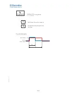
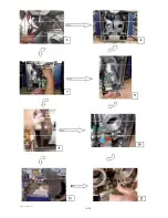
5-8 ADJUST THE SPRINGS (See page 23)
Switch off and disconnect the machine.
Open the back panel of the tilting box ( items100 and 101 on
articulation exploded view ).
Disengage the gas spring (item 88 on articulation exploded
view) on one of its ends.
Adjust the springs (item 86 on articulation exploded
view) in the way that their pretension lifts the lid 100mm
+/- 10mm (7,5’’+/-0,4’’) on the front without the gas
spring working.
Reengage the gas spring.
Make a functioning test of the lid opening.
Reinstall the back panel of the tilting box.
(See page 23)
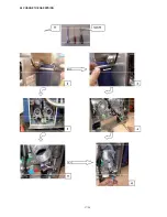
5.9 CHANGE THE GAZ SPRING (see page 26)
190+/-
10mm
100mm +/- 10mm
(7,5’’+/-0,4’’)
Summary of Contents for HSG Panini
Page 1: ...Service Manual GB 07 2009 HSG Panini Service manual ...
Page 2: ...2 2 50mm 50mm 7 5 190mm ...
Page 3: ......
Page 4: ......
Page 11: ...7 38 Explanation on software settings EU Version U207 ...
Page 12: ...8 38 Explanation on software settings US Version U202 U208 ...
Page 28: ...24 38 HSPP tech GB 03 09 ADJUST THE SPRINGS ...
Page 29: ...25 38 HSPP tech GB 03 09 ...
Page 30: ...26 38 ...
Page 31: ...27 38 5 9 CHANGE THE GAS SPRING ...
Page 32: ...28 38 ...
Page 33: ...29 38 ...
Page 41: ...37 38 ...
Page 43: ......
Page 49: ...Vue éclatée Couvercle Cover exploded view Explosionszeichnung Haube F HSPP FR 03 09 ...
Page 51: ...Esploso coperchio Despiece tapa Sprängskiss lock H HSPP FR 03 09 ...
Page 53: ...Vue éclatée Articulation Hinge exploded view Explosionszeichnung Gelenk J HSPP FR 06 09 ...
Page 55: ...Esploso articolazione Despiece articulación Sprängskiss Rotation L HSPP FR 06 09 ...
Page 59: ...Vue éclatée Electrique Electric exploded view Explosionszeichnung Elektrik P HSPP FR 03 09 ...
Page 61: ...Esploso elettronica Despiece electricidad Sprängskiss elektronik R HSPP FR 03 09 ...
Page 64: ......


