C
C
Always isolate the cooker from the electricity
supply, shut off the gas supply temporarily
and proceed as follows.
- change the injectors,
- adjust the minimum flow of the burners.
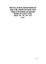
REPLACEMENT OF COOKTOP INJECTORS
To change the cooktop injectors, proceed as
follows: remove the grids, remove burners
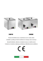
and flame-spreaders (see fig. 13), change
the injector (see fig. 14 and replace it with
another one suitable for the new type of gas
(see table D).
Re-assemble everything in reverse order,
ensuring you position the flame-spreader
correctly.
Fig. 15
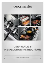
MINIMUM FLOW ADJUSTMENT FOR
COOKTOP TAPS
To adjust the minimum, proceed as follows:
switch the burner on, and turn the knob
towards the minimum flow position
.
Remove the knob from the tap, introduce a
small screwdriver in to the tap rod (fig. 15).
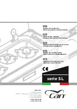
Attention: in taps with security valve, the
minimum adjustment screw
Z
is placed
outside the tap rod (fig. 16).
Loosen the adjustment screw in order to
increase the flow or tighten it to decrease the
flow.
The proper adjustment is obtained when the
flame is approximately 3 or 4 mm in length.
For butane/propane gas, the adjustment screw
must be fully screwed down.
Make sure that the flame does not go out
when passing quickly from the max. flow
to the minimum flow .
Assemble the knob again.
Fig. 16
Z
GB
TAB. D
Cat. II 2H3+
GENERAL INJECTORS TABLE
Kind of gas
mbar
Nozzle
Burners
Power
KW
N° max.
128
Rapid
3,00
NATURAL 20 101
Semi rapid
1,75
G 20 77
Auxiliary
1,00
141
Triple crown
3,80
BUTANE 28-30 87
Rapid
3,00
G 30 66
Semi rapid
1,75
PROPANE 37 50
Auxiliary
1,00
G 31 96
Triple crown
3,80
Fig. 13
Fig. 14
C = Injector triple crown
17
GAS ADJUSTMENT