


CAN S.r.l.
Via Nazionale 65,
25080 - Puegnago del Garda (BS) ITALY
T. +39 0365 555909
F. +39 0365 651822
www.cansrl.com
DE
HANDBUCH FÜR INSTALLATION,
GEBRAUCH UND WARTUNG
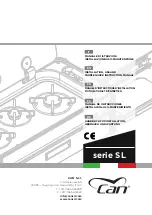
serie SL
IT
MANUALE DI ISTRUZIONI
INSTALLAZIONE-USO-MANUTENZIONE
EN
INSTALLATION, USE AND
MAINTENANCE INSTRUCTION MANUAL
FR
MANUEL D’INSTRUCTIONS D’INSTALLATION-
D’UTILISATION-ET D’ENTRETIEN
ES
MANUAL DE INSTRUCCIONES
INSTALACIÓN-USO-MANTENIMIENTO
Summary of Contents for SL Series
Page 4: ...4 ITALIANO PAGINA LASCIATA INTENZIONALMENTE BIANCA...
Page 76: ...4 ENGLISH PAGE LEFT INTENTIONALLY BLANK...
Page 148: ...4 FRAN AIS PAGE LAISS E INTENTIONNELLEMENT BLANCHE...
Page 220: ...4 ESPA OL P GINA DEJADA EN BLANCO INTENCIONALMENTE...
Page 292: ...4 DEUTSCH ABSICHTLICH LEER GELASSENE SEITE...
Page 362: ......