


3
"
ECO DRYING
" button
- Press to exclude the drying function. The LED lights when ECO DRYING has been selected.
- Press again to reset the appliance to normal drying. The LED switches off.
"
ECO DRYING
" LED
(green)
-
ON:
ECO DRYING activated
-
OFF:
ECO DRYING disactivated
4
"
DELAYED START
" button
- Press to enter the number of hours of delayed start for the programme selected
- The LED flashes while the DELAYED START option is being selected
- Transmits a signal which is displayed on the "
DIGIT
" window in the form of a number (from
1
to
9
)
"
DELAYED START
" LED
(green)
-
FLASHES
while the number of hours is being selected
-
LIT
while the countdown is in progress
-
OFF
during selection and execution of the washing programme
5
"
CANCEL
" button
- This button is enabled only when the door is open
- Must be held down for at least
2 seconds
- In the Programme Selection phase, cancels all selections entered
- If pressed while the programme is in progress, interrupts and cancels the cycle
SELECTING THE WATER HARDNESS LEVEL
OPEN THE DOOR:
Set the appliance to the Programme Selection phase
SWITCH ON THE DISHWASHER
:
If necessary, press the "
ON/OFF
" button.
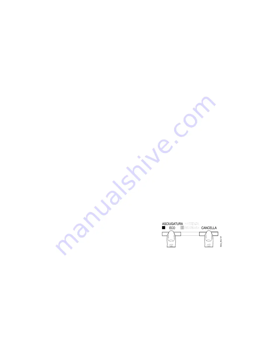
- Press the "
ECO DRYING
" and "
CANCEL
" buttons (
3 + 5
)
simultaneously, and hold them down for
5 seconds
until
the previously-selected hardness level (
0
to
9
) is displayed
on the
DIGIT
window.
- To modify the hardness level, press the "
ECO DRYING
"
button (
3
) while the corresponding LED is flashing.
The setting increases by one level each time the button is
pressed.
-
5 seconds
after pressing the button for the last time, the hardness level displayed on the
DIGIT
window
is stored in memory.
The appliance automatically returns to the Programme Selection phase.
- 33 -
Summary of Contents for 60 cm Series
Page 2: ... 2 ...
Page 8: ...STRUCTURE 8 ...
Page 9: ...INTERIOR OF TUB SUMP 9 ...
Page 10: ...HYDRAULIC ELECTRICAL COMPONENTS 10 ...
Page 15: ...WATER FILL CIRCUIT 15 ...
Page 17: ...LEVEL CONTROL CIRCUIT 17 ...
Page 19: ...WATER SOFTENING CIRCUIT 19 ...
Page 21: ...REGENERATION SYSTEM CIRCUIT DIAGRAM 21 ...
Page 28: ...FUNCTIONAL CIRCUIT DIAGRAM STANDARD TIMER 28 ...
Page 29: ...TIMER OPERATION STANDARD 29 ...
Page 30: ...FUNCTIONAL CIRCUIT DIAGRAM MEDIUM DE LUXE TIMER 30 ...
Page 31: ...TIMER OPERATION MEDIUM DE LUXE 31 ...
Page 34: ...FUNCTIONAL CIRCUIT DIAGRAM ITRONIC 34 ...
Page 35: ...CYCLE SEQUENCE ITRONIC 35 ...


