


3
IMTP(D) 2.2 – ITTP(D) 2.2/4.0/5.5/7.5 - ELECTROIL
ENG
1.
GENERAL DATA
With this manual, we would like to give you the most important information about the correct use and maintenance
of the inverter.
The devices described in this manual are:
IMTP2.2M - IMTPD2.2M
: Single-phase Inverter for pump, max 2.2 kW (3 Hp)
ITTP2.2M - ITTPD2.2M
: Three-phase Inverter for pump, max 2.2 kW (3 Hp)
ITTP4.0M - ITTPD4.0M/W
: Three-phase Inverter for pump, max 4 kW (5.5 Hp)
ITTP5.5M - ITTPD5.5M/W:
Three-phase Inverter for pump, max 5.5 kW (7.5 Hp)
ITTP7.5M - ITTPD7.5W:
Three-phase Inverter for pump, max 7.5 kW (10 Hp)
The models for circulation pump control (D) differ from the models for standard centrifugal pumps for the
accessories and for the output cables of the pressure transducers. The software on both inverter models is the
same and is always marked with the letter D.
In models for standard centrifugal pumps (absolute pressure control) it is always supplied a pressure transducer
K16, 16 Bar; in the models for circulation pumps (differential pressure control) the pressure transducers, suitable
for high temperature, with reduced pressure range and high precision (K3T 3 Bar or K5T from 5 bars) are sold
separately (N°2 transducers required: one for the delivery and one for the inlet).
This inverters are devices specially designed for centrifugal and circulating pump control, single type or twin/group
type, thanks to a perfect feed-back of the absolute pressure or the differential pressure: it assures energy saving
and it has many programmable functions, that are not in the other common directly supplied motor pumps.
The following instructions and rules about the standard configuration are as follows.
If you require technical assistance regarding specific parts at Service Sales please do specify the exact type of
the inverter, followed by the serial number of the model.
2.
WORKING OPERATIONS
This Pump–Inverter system is made up by a centrifugal pump, that is moved by an asynchronous motor. This
system has to keep the absolute delivery pressure or the differential pressure (from delivery and inlet) steady,
independently from the flow (consistent with the maximum load applicable to the motor, otherwise the maximum
current absorption).
The input and output pressure are monitored by two pressure transducer, with 4-20mA output. The control logic
works with a 15V output that supplies the pressure transducers.
DRY WORKING: to prevent the pump from working when there is a suction condition problem, caused by an
insufficient inlet flow, the system reads the motor power and power factor, and if its are under setting values with
a particular low pressure condition , it switches off the pump, and an advise appears on display.
The motor pump electric protection is controlled by the limitation of the current absorption (programmable). When
the current protection is on, an alarm appears on display. When the condition disappear, the system restart with
the normal functioning.
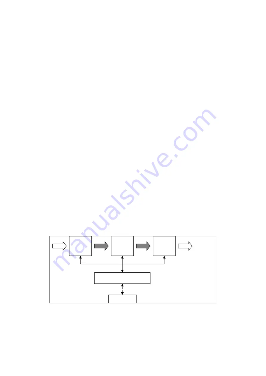
2.1 Structure of a frequency converter
Figure 1: structure of a frequency converter
c.a.
Alternative current
c.c.
Direct current
RAD
Rectifier
INT
IGBT intermediate driver circuit
INV
IGBT bridge three-phase inverter
M
Motor
CONT
Control logic by micro-processor
RAD
INT
INV
CONT
TRASM
1 x 230V/
3 x 400V
3 x 400V
or
3 x 230V
c.c.
c.c.
c.a.
M