


© ElectroCraft 2022
12
CPP-x06V48A-SA-CAN Drive User Manual
3
Product Overview
This manual describes the installation and operation of the CPP-x06V48A-SA-CAN digital servo-amplifier
manufactured by ElectroCraft Inc.
3.1
Key Features
Features of CPP-x06V48A-SA-CAN drive:
•
+12 to +48 VDC power supply input.
•
6 Amps Continuous, 6 Amps Peak for CPP-B06V48A-SA-CAN or 15 Amps Peak CPP-A06V48A-
SA-CAN (2 seconds).
•
2 and 4 quadrant modes.
•
Sinusoidal and Trapezoidal commutation modes.
•
20 kHz, 40 kHz and 80 kHz of programmable PWM frequency options.
•
Current, Speed, Position and Position with Speed modes of operation.
•
USB Communication.
•
High Speed CAN Communication up to 1Mbps
•
Drive status diagnostics.
•
+/-10V Analog command input.
•
Digital step and direction input.
•
+/-10V Analog output (configurable).
•
Encoder mode for low speed performance.
•
Digital input for Capture feature for encoder location.
•
Digital output signal to engage eBrake.
•
BLDC, PMDC and Stepper motor control.
•
Halls only operation mode for BLDC motor.
•
IxR speed feedback estimator mode for PMDC motor.
•
Integrated circuit for brake regeneration.
•
+/- Travel limit inputs.
•
Configurable ramp for current and speed.
•
97% efficiency at full load.
•
Selectable software protection options.
•
Windows®-based
ElectroCraft
CompleteArchitect™
set-up and tuning utility software included.
Note:
The CPP-x06V48A-SA-CAN drive can be configured by the software through USB even when
there is no power supply provided.
3.2
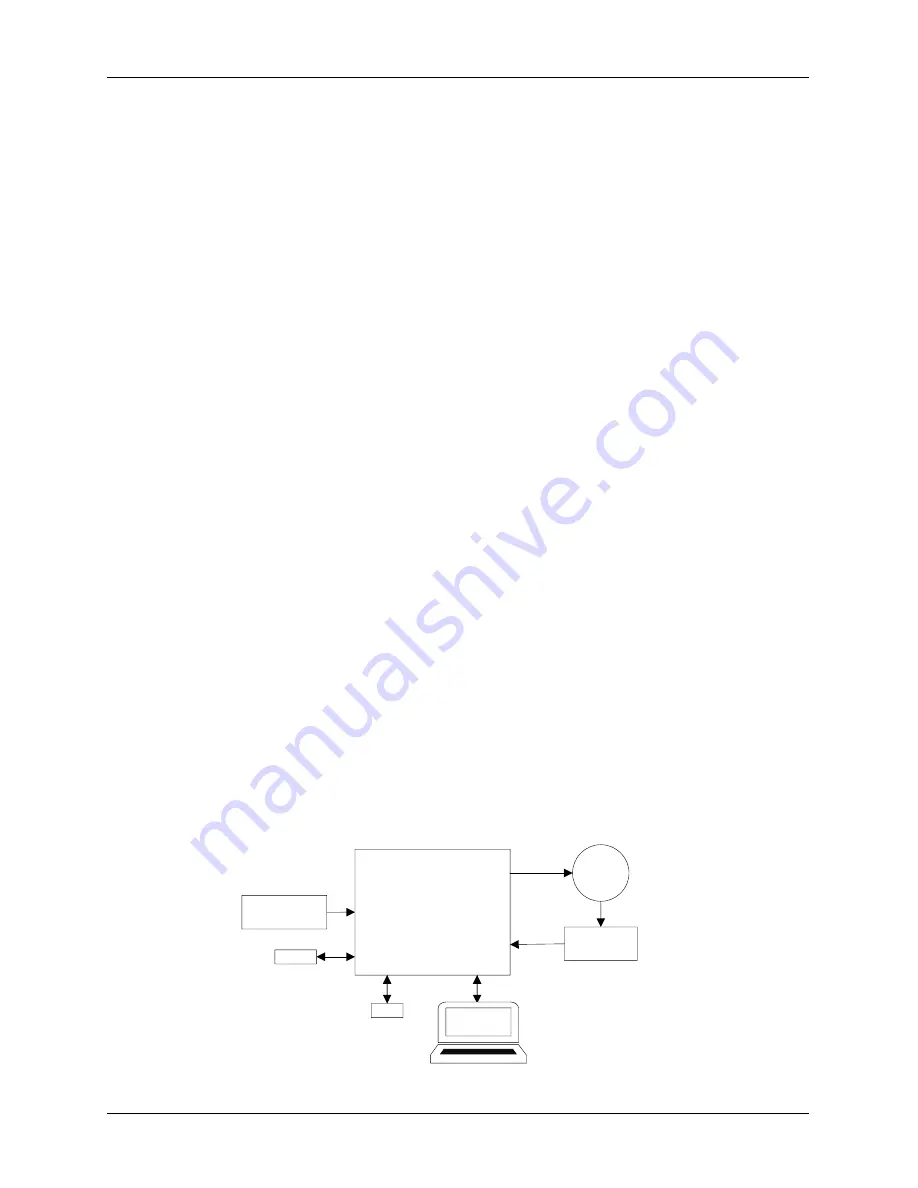
Simplified System Block Diagram
Overall system of CPP-x06V48A-SA-CAN is shown in Figure 1. The drive is configured using the software
to operate the motor according to its application.
Drive
Power Supply
Motor
Feedback
I/O
PC Software
CAN
USB
Figure 1: Overall drive system block diagram


