


12-34
CONTROL SYSTEM
SM DELTA 1-E.0 GB
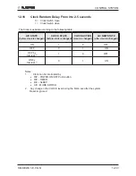
12.2 System Diagnostics
Pressing Mode button for 5-10 seconds in SB or any other operation mode will activate
diagnostic mode by the acknowledgment of 3 short beeps and lighting of COOL and
HEAT LEDs.
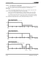
In diagnostic mode, system problems will be indicated by blinking of Heat & Cool LEDs.
The coding method will be as follow:
Heat led will blink 5 times in 5 seconds, and then will be shut off for the next 5 seconds.
Cool led will blink during the same 5 seconds according to the following table:
No
Problem
○
○
○
○
○
1
RT1 is disconnected
○
●
●
●
●
2
RT1 is shorted
○
●
●
●
○
3
(Reserved)
○
●
●
○
●
4
RT2 is disconnected
●
○
●
●
●
5
RT2 is shorted
●
○
●
●
○
6
(Reserved)
●
○
●
○
●
7
RT2 temp reading doesn’t change
●
○
●
○
○
8
RT3 is disconnected
●
●
○
●
●
9
RT3 is shorted
●
●
○
●
○
10
(Reserved)
●
●
○
○
●
11
RT3 temp reading doesn’t change
●
●
○
○
○
12
RT2 & RT3 temp reading doesn’t change
●
○
○
○
○
○ - ON,
● - OFF
Notes:
1. If faults occur in more than one thermistor (except case number 12 on
the
table above), only one fault will be indicated according to the following
order:
RT3, RT2, RT1.
2. A/C will jump out to normal mode if sending a command by the R/C in
the
system diagnostics mode. If this command from the R/C contain a Group
ID, this
ID will become the new Group ID of the ELCON unit.
Summary of Contents for DELTA 18
Page 14: ...4 2 OUTLINE DIMENSIONS SM DELTA 1 E 0 GB 4 3 Outdoor Unit OU7 24 OU7 24Z...
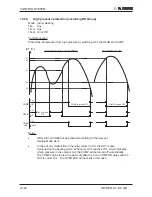
Page 21: ...5 7 PERFORMANCE DATA PRESSURE CURVES SM DELTA 1 E 0 GB 5 6 Pressure Curves 5 6 1 Cooling...
Page 22: ...5 8 PERFORMANCE DATA PRESSURE CURVES SM DELTA 1 E 0 GB 5 6 2 Heating...
Page 31: ...8 1 WIRING DIAGRAMS SM DELTA 1 E 0 GB 8 WIRING DIAGRAMS 8 1 Indoor Unit DELTA 18 21 24...
Page 32: ...8 2 WIRING DIAGRAMS SM DELTA 1 E 0 GB 8 2 Outdoor Unit GC 18 1PH R410A...
Page 33: ...8 3 WIRING DIAGRAMS SM DELTA 1 E 0 GB 8 3 Outdoor Unit GC 24 1PH R410A...
Page 34: ...8 4 WIRING DIAGRAMS SM DELTA 1 E 0 GB 8 4 Outdoor Unit OU7 24 1PH R410A...
Page 35: ...8 5 WIRING DIAGRAMS SM DELTA 1 E 0 GB 8 5 Outdoor Unit OU7 24 3PH R410A...
Page 36: ...8 6 WIRING DIAGRAMS SM DELTA 1 E 0 GB 8 6 Outdoor Unit OU7 24Z R410A...
Page 39: ...10 2 REFRIGERATION DIAGRAMS Service Manual ALPHA 10 1 2 DELTA 24 OU7 24 R410A...
Page 40: ...10 3 REFRIGERATION DIAGRAMS SM DELTA 1 E 0 GB 10 1 3 DELTA 24 OU7 24Z R410A...
Page 81: ...14 3 EXPLODED VIEWS AND SPARE PARTS LISTS SM DELTA 1 E 0 GB 14 3 Outdoor Unit GC 18 ST...
Page 83: ...14 5 EXPLODED VIEWS AND SPARE PARTS LISTS SM DELTA 1 E 0 GB 14 5 Outdoor Unit GC 18 RC...
Page 85: ...14 7 EXPLODED VIEWS AND SPARE PARTS LISTS SM DELTA 1 E 0 GB 14 7 Outdoor Unit GC 21 RC...
Page 87: ...14 9 EXPLODED VIEWS AND SPARE PARTS LISTS SM DELTA 1 E 0 GB 14 9 Outdoor Unit GC 21 ST...
Page 89: ...14 11 EXPLODED VIEWS AND SPARE PARTS LISTS SM DELTA 1 E 0 GB 14 11 Outdoor Unit GCN 12 RC...
Page 91: ...14 13 EXPLODED VIEWS AND SPARE PARTS LISTS SM DELTA 1 E 0 GB 14 13 Outdoor Unit GC 24 RC...
Page 93: ...14 15 EXPLODED VIEWS AND SPARE PARTS LISTS SM DELTA 1 E 0 GB 14 15 Outdoor Unit OU7 24 RC 1PH...
Page 95: ...14 17 EXPLODED VIEWS AND SPARE PARTS LISTS SM DELTA 1 E 0 GB 14 17 Outdoor Unit OU7 24 ST 1PH...
Page 99: ...14 21 EXPLODED VIEWS AND SPARE PARTS LISTS SM DELTA 1 E 0 GB 14 21 Outdoor Unit OU7 24 RC 3PH...
Page 101: ...14 23 EXPLODED VIEWS AND SPARE PARTS LISTS SM DELTA 1 E 0 GB 14 23 Outdoor Unit OU7 24 ST 3PH...
Page 106: ...15 4 OPTIONAL ACCESSORIES SM DELTA 1 E 0 GB...
Page 107: ...15 5 OPTIONAL ACCESSORIES SM DELTA 1 E 0 GB...
Page 108: ...15 6 OPTIONAL ACCESSORIES SM DELTA 1 E 0 GB...


