


12-23
CONTROL SYSTEM
SM DELTA 1-E.0 GB
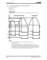
12.10
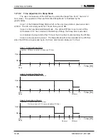
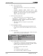
Timer
Mode:
Any
Temp. Selected desired temp
Fan:
Any
Timer: Timer On, Timer Off
I Feel: On or Off
Control
function
•
Starts or stops the unit operation after pre-set time. If RC-1 is used,
the timer setting will be (0.5 - 24 Hr) from the moment the timer is set.
The minimum resolution is 30 minutes.
If RC-2 or later version of remote controls is used, the timer
setting will be (0:00 - 23:50) real time with 10 minutes resolution.
•
After power failure, all pre-set timers are cleared. The system is
forced to STBY mode and the Timer LED indicator is blinked to
indicate the situation. The LED keeps blinking until the timer settings
can be reloaded from a R/C message.
Note: If all timers are inactive, the system will not be forced
OFF after the power failure. The last OPER/STBY status will
be loaded from the EEP instead.
•
When the A/C receives any valid message from a R/C, the current
ON/OFF timer settings will be replaced by the new timer settings in
the R/C message.
Note: The following timer related operations will not affect the
A/C operating mode (Heat/Cool/Auto/Dry/Fan) setting.
•
Set ON/OFF timer
•
Clear ON/OFF timer
•
R/C ON Timer is time-up
•
R/C OFF Timer is time-up
E.g. When a STBY A/C unit (with Cool Mode setting in its EEP) is
turned on by the ON-TIMER of a R/C with heat mode setting,
the A/C will start in Cool Mode.
Summary of Contents for DELTA 18
Page 14: ...4 2 OUTLINE DIMENSIONS SM DELTA 1 E 0 GB 4 3 Outdoor Unit OU7 24 OU7 24Z...
Page 21: ...5 7 PERFORMANCE DATA PRESSURE CURVES SM DELTA 1 E 0 GB 5 6 Pressure Curves 5 6 1 Cooling...
Page 22: ...5 8 PERFORMANCE DATA PRESSURE CURVES SM DELTA 1 E 0 GB 5 6 2 Heating...
Page 31: ...8 1 WIRING DIAGRAMS SM DELTA 1 E 0 GB 8 WIRING DIAGRAMS 8 1 Indoor Unit DELTA 18 21 24...
Page 32: ...8 2 WIRING DIAGRAMS SM DELTA 1 E 0 GB 8 2 Outdoor Unit GC 18 1PH R410A...
Page 33: ...8 3 WIRING DIAGRAMS SM DELTA 1 E 0 GB 8 3 Outdoor Unit GC 24 1PH R410A...
Page 34: ...8 4 WIRING DIAGRAMS SM DELTA 1 E 0 GB 8 4 Outdoor Unit OU7 24 1PH R410A...
Page 35: ...8 5 WIRING DIAGRAMS SM DELTA 1 E 0 GB 8 5 Outdoor Unit OU7 24 3PH R410A...
Page 36: ...8 6 WIRING DIAGRAMS SM DELTA 1 E 0 GB 8 6 Outdoor Unit OU7 24Z R410A...
Page 39: ...10 2 REFRIGERATION DIAGRAMS Service Manual ALPHA 10 1 2 DELTA 24 OU7 24 R410A...
Page 40: ...10 3 REFRIGERATION DIAGRAMS SM DELTA 1 E 0 GB 10 1 3 DELTA 24 OU7 24Z R410A...
Page 81: ...14 3 EXPLODED VIEWS AND SPARE PARTS LISTS SM DELTA 1 E 0 GB 14 3 Outdoor Unit GC 18 ST...
Page 83: ...14 5 EXPLODED VIEWS AND SPARE PARTS LISTS SM DELTA 1 E 0 GB 14 5 Outdoor Unit GC 18 RC...
Page 85: ...14 7 EXPLODED VIEWS AND SPARE PARTS LISTS SM DELTA 1 E 0 GB 14 7 Outdoor Unit GC 21 RC...
Page 87: ...14 9 EXPLODED VIEWS AND SPARE PARTS LISTS SM DELTA 1 E 0 GB 14 9 Outdoor Unit GC 21 ST...
Page 89: ...14 11 EXPLODED VIEWS AND SPARE PARTS LISTS SM DELTA 1 E 0 GB 14 11 Outdoor Unit GCN 12 RC...
Page 91: ...14 13 EXPLODED VIEWS AND SPARE PARTS LISTS SM DELTA 1 E 0 GB 14 13 Outdoor Unit GC 24 RC...
Page 93: ...14 15 EXPLODED VIEWS AND SPARE PARTS LISTS SM DELTA 1 E 0 GB 14 15 Outdoor Unit OU7 24 RC 1PH...
Page 95: ...14 17 EXPLODED VIEWS AND SPARE PARTS LISTS SM DELTA 1 E 0 GB 14 17 Outdoor Unit OU7 24 ST 1PH...
Page 99: ...14 21 EXPLODED VIEWS AND SPARE PARTS LISTS SM DELTA 1 E 0 GB 14 21 Outdoor Unit OU7 24 RC 3PH...
Page 101: ...14 23 EXPLODED VIEWS AND SPARE PARTS LISTS SM DELTA 1 E 0 GB 14 23 Outdoor Unit OU7 24 ST 3PH...
Page 106: ...15 4 OPTIONAL ACCESSORIES SM DELTA 1 E 0 GB...
Page 107: ...15 5 OPTIONAL ACCESSORIES SM DELTA 1 E 0 GB...
Page 108: ...15 6 OPTIONAL ACCESSORIES SM DELTA 1 E 0 GB...


