


12-32
CONTROL SYSTEM
SM DELTA 1-E.0 GB
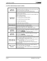
12.15 On Unit Indicators and Controls
STAND BY
INDICATOR
Lights up when the Air Conditioner is connected to power and
ready to receive the R/C commands
Blinks continuously in case of any thermistor failure.
OPERATION
INDICATOR
Lights up during operation.
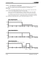
Blinks for 300 ms, to announce that a R/C infrared signal has
been received and stored.
Blinks continuously during
•
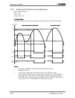
OCT High Pressure Protection Mode
•
ICT High Pressure Protection Mode
•
Deicing in Heating Mode
•
Water Over Flow in ECC Model
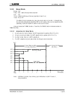
TIMER INDICATOR
Lights up during Timer and Sleep operation.
FILTER INDICATOR
Lights up when Air Filter needs to be cleaned.
Blinks during Water Over Flow in MBX/P2000 models.
COOLING
INDICATOR
Lights up when system is switched to Cool Mode by using the
Mode Switch on the unit.
Show the thermistor status in Diagnostic Mode
HEATING
INDICATOR
Lights up when system is switched Heat Mode by using the
Mode Switch on the unit.
Show the thermistor status in Diagnostic Mode.
MODE BUTTON
(Cool, Heat, SB)
Use to cycle the operation mode of the A/C unit among COOL,
HEAT and SB modes, without using the R/C.
Every time this switch is pressed, the next operation mode is
selected, in this order :
SB
Cool Mode
Heat Mode
SB
...
Press this button continuously for 5 sec or more to start the
Diagnostic Mode.
RESET / FILTER
BUTTON
When the Filter LED is ON, press to turn off the Filter LED
after a clean filter has been reinstalled.
When the Filter LED is OFF, use this button to enable/disable
the buzzer announcer.
Summary of Contents for DELTA 18
Page 14: ...4 2 OUTLINE DIMENSIONS SM DELTA 1 E 0 GB 4 3 Outdoor Unit OU7 24 OU7 24Z...
Page 21: ...5 7 PERFORMANCE DATA PRESSURE CURVES SM DELTA 1 E 0 GB 5 6 Pressure Curves 5 6 1 Cooling...
Page 22: ...5 8 PERFORMANCE DATA PRESSURE CURVES SM DELTA 1 E 0 GB 5 6 2 Heating...
Page 31: ...8 1 WIRING DIAGRAMS SM DELTA 1 E 0 GB 8 WIRING DIAGRAMS 8 1 Indoor Unit DELTA 18 21 24...
Page 32: ...8 2 WIRING DIAGRAMS SM DELTA 1 E 0 GB 8 2 Outdoor Unit GC 18 1PH R410A...
Page 33: ...8 3 WIRING DIAGRAMS SM DELTA 1 E 0 GB 8 3 Outdoor Unit GC 24 1PH R410A...
Page 34: ...8 4 WIRING DIAGRAMS SM DELTA 1 E 0 GB 8 4 Outdoor Unit OU7 24 1PH R410A...
Page 35: ...8 5 WIRING DIAGRAMS SM DELTA 1 E 0 GB 8 5 Outdoor Unit OU7 24 3PH R410A...
Page 36: ...8 6 WIRING DIAGRAMS SM DELTA 1 E 0 GB 8 6 Outdoor Unit OU7 24Z R410A...
Page 39: ...10 2 REFRIGERATION DIAGRAMS Service Manual ALPHA 10 1 2 DELTA 24 OU7 24 R410A...
Page 40: ...10 3 REFRIGERATION DIAGRAMS SM DELTA 1 E 0 GB 10 1 3 DELTA 24 OU7 24Z R410A...
Page 81: ...14 3 EXPLODED VIEWS AND SPARE PARTS LISTS SM DELTA 1 E 0 GB 14 3 Outdoor Unit GC 18 ST...
Page 83: ...14 5 EXPLODED VIEWS AND SPARE PARTS LISTS SM DELTA 1 E 0 GB 14 5 Outdoor Unit GC 18 RC...
Page 85: ...14 7 EXPLODED VIEWS AND SPARE PARTS LISTS SM DELTA 1 E 0 GB 14 7 Outdoor Unit GC 21 RC...
Page 87: ...14 9 EXPLODED VIEWS AND SPARE PARTS LISTS SM DELTA 1 E 0 GB 14 9 Outdoor Unit GC 21 ST...
Page 89: ...14 11 EXPLODED VIEWS AND SPARE PARTS LISTS SM DELTA 1 E 0 GB 14 11 Outdoor Unit GCN 12 RC...
Page 91: ...14 13 EXPLODED VIEWS AND SPARE PARTS LISTS SM DELTA 1 E 0 GB 14 13 Outdoor Unit GC 24 RC...
Page 93: ...14 15 EXPLODED VIEWS AND SPARE PARTS LISTS SM DELTA 1 E 0 GB 14 15 Outdoor Unit OU7 24 RC 1PH...
Page 95: ...14 17 EXPLODED VIEWS AND SPARE PARTS LISTS SM DELTA 1 E 0 GB 14 17 Outdoor Unit OU7 24 ST 1PH...
Page 99: ...14 21 EXPLODED VIEWS AND SPARE PARTS LISTS SM DELTA 1 E 0 GB 14 21 Outdoor Unit OU7 24 RC 3PH...
Page 101: ...14 23 EXPLODED VIEWS AND SPARE PARTS LISTS SM DELTA 1 E 0 GB 14 23 Outdoor Unit OU7 24 ST 3PH...
Page 106: ...15 4 OPTIONAL ACCESSORIES SM DELTA 1 E 0 GB...
Page 107: ...15 5 OPTIONAL ACCESSORIES SM DELTA 1 E 0 GB...
Page 108: ...15 6 OPTIONAL ACCESSORIES SM DELTA 1 E 0 GB...


