


12-30
CONTROL SYSTEM
SM DELTA 1-E.0 GB
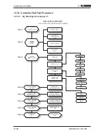
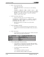
d. STEP 4 : AUTO LED WALK TEST.
•
All the LEDS will turn OFF.
•
All the LEDS will turn ON for 1 second one by one in the following
sequence:
STAND-BY
OPERATE
TIMER
FILTER
COOL
HEAT.
•
In PRX all the LEDS will turn ON for 1 second one by one in the following
sequence : 18 °c
20 °c
22 °c
24 °c
26 °c
28 °c
30 °c
High IFAN
Auto IFAN
Med IFAN
Low IFAN
STAND-BY
TIMER
FILTER
COOL
HEAT.
e. STEP 5: AUTO REALY WALK TEST:
•
All relays will energize one by one in the following sequence:
COMPRESSOR
OUTDOOR FAN
R. V.
HEATER 1
HEATER 2
INDOOR WATER PUMP
SWING or OUTDOOR WATER PUMP
INDOOR FAN: LOW
MID
HIGH.
•
When the relay walk test is completed, the next test will start
automatically.
f.
STEP 6: FREQUENCY TESTING:
•
If the frequency measuring process fails the COOL LED will turn ON.
In order to move to the next step, press ON/OFF button on the remote
control.
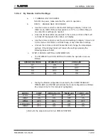
g. STEP
7:
INPUT
TEST.
•
The test purpose is to check the analog real time indicators (thermistors,
LEVEL and clock) according to the table below.
LED Indicator
Condition for LED to be ON
STBY LED
Room thermistor
≠
25°c
OPER LED
Indoor coil thermistor
≠
25°c
TIMER LED
Outdoor coil thermistor
≠
25°c
FILTER LED
Clock
COOL LED
LEVEL 2&3
HEAT LED
LEVEL 4
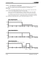
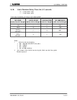
h. STEP 8: TIMING RESET TEST (WATCH DOG).
•
The test purpose is to verify that the CPU rise time after power failure
is between 1 to 3 sec, test results are indicated on the LEDS : STAND-
BY,OPER, TIMER and FILTER turning ON one by one.
•
The results of the test are coded as follows:
Pass condition:
1 sec - STAND-BY and OPER are turned ON
2 sec - STAND-BY, OPER and TIMER are turned ON
Summary of Contents for DELTA 18
Page 14: ...4 2 OUTLINE DIMENSIONS SM DELTA 1 E 0 GB 4 3 Outdoor Unit OU7 24 OU7 24Z...
Page 21: ...5 7 PERFORMANCE DATA PRESSURE CURVES SM DELTA 1 E 0 GB 5 6 Pressure Curves 5 6 1 Cooling...
Page 22: ...5 8 PERFORMANCE DATA PRESSURE CURVES SM DELTA 1 E 0 GB 5 6 2 Heating...
Page 31: ...8 1 WIRING DIAGRAMS SM DELTA 1 E 0 GB 8 WIRING DIAGRAMS 8 1 Indoor Unit DELTA 18 21 24...
Page 32: ...8 2 WIRING DIAGRAMS SM DELTA 1 E 0 GB 8 2 Outdoor Unit GC 18 1PH R410A...
Page 33: ...8 3 WIRING DIAGRAMS SM DELTA 1 E 0 GB 8 3 Outdoor Unit GC 24 1PH R410A...
Page 34: ...8 4 WIRING DIAGRAMS SM DELTA 1 E 0 GB 8 4 Outdoor Unit OU7 24 1PH R410A...
Page 35: ...8 5 WIRING DIAGRAMS SM DELTA 1 E 0 GB 8 5 Outdoor Unit OU7 24 3PH R410A...
Page 36: ...8 6 WIRING DIAGRAMS SM DELTA 1 E 0 GB 8 6 Outdoor Unit OU7 24Z R410A...
Page 39: ...10 2 REFRIGERATION DIAGRAMS Service Manual ALPHA 10 1 2 DELTA 24 OU7 24 R410A...
Page 40: ...10 3 REFRIGERATION DIAGRAMS SM DELTA 1 E 0 GB 10 1 3 DELTA 24 OU7 24Z R410A...
Page 81: ...14 3 EXPLODED VIEWS AND SPARE PARTS LISTS SM DELTA 1 E 0 GB 14 3 Outdoor Unit GC 18 ST...
Page 83: ...14 5 EXPLODED VIEWS AND SPARE PARTS LISTS SM DELTA 1 E 0 GB 14 5 Outdoor Unit GC 18 RC...
Page 85: ...14 7 EXPLODED VIEWS AND SPARE PARTS LISTS SM DELTA 1 E 0 GB 14 7 Outdoor Unit GC 21 RC...
Page 87: ...14 9 EXPLODED VIEWS AND SPARE PARTS LISTS SM DELTA 1 E 0 GB 14 9 Outdoor Unit GC 21 ST...
Page 89: ...14 11 EXPLODED VIEWS AND SPARE PARTS LISTS SM DELTA 1 E 0 GB 14 11 Outdoor Unit GCN 12 RC...
Page 91: ...14 13 EXPLODED VIEWS AND SPARE PARTS LISTS SM DELTA 1 E 0 GB 14 13 Outdoor Unit GC 24 RC...
Page 93: ...14 15 EXPLODED VIEWS AND SPARE PARTS LISTS SM DELTA 1 E 0 GB 14 15 Outdoor Unit OU7 24 RC 1PH...
Page 95: ...14 17 EXPLODED VIEWS AND SPARE PARTS LISTS SM DELTA 1 E 0 GB 14 17 Outdoor Unit OU7 24 ST 1PH...
Page 99: ...14 21 EXPLODED VIEWS AND SPARE PARTS LISTS SM DELTA 1 E 0 GB 14 21 Outdoor Unit OU7 24 RC 3PH...
Page 101: ...14 23 EXPLODED VIEWS AND SPARE PARTS LISTS SM DELTA 1 E 0 GB 14 23 Outdoor Unit OU7 24 ST 3PH...
Page 106: ...15 4 OPTIONAL ACCESSORIES SM DELTA 1 E 0 GB...
Page 107: ...15 5 OPTIONAL ACCESSORIES SM DELTA 1 E 0 GB...
Page 108: ...15 6 OPTIONAL ACCESSORIES SM DELTA 1 E 0 GB...


