background image

51

M

EASURING


WELDED


MESH


AND


JOINED


BARS

R

17 MEASURING WELDED MESH AND JOINED BARS

The  procedures  for  locating  and  measuring  depth  of  cover  of  welded  mesh  and  joined  bars  are
similar to those for reinforcement bars as described in sections 5and 9 (pages 18 to 24 and 27
to  30).  This  section  highlights  the  additional  factors  which  must  be  considered  when  measuring
welded mesh or joined bars.

When  searching  for  isolated  reinforcing  bars,  the  Covermeter  induces  eddy  currents  within  the
individual  bars.  Welded  mesh  reinforcements  however  create  current  loops  which  produce
additional strong signals.

When searching for welded mesh reinforcements, it is common to encounter three levels of signal:

Very strong signals

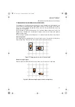
Very  strong  signals  are  obtained  when  the  search  head  is  across  the  centre  bar  of  a  double  or
‘figure-of-eight’ loop. These locations must not be used for cover measurements.

Figure 27. Strong signals at centre of ‘figure-of-eight’

Minimum strength signals

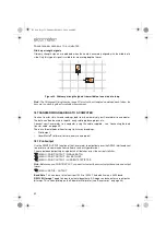
Minimum signals are obtained when the search head is over the centre of a single loop.

Figure 28. Minimum strength signals at centre of single loop

331.book  Page 51  Thursday, March 12, 2009  9:46 PM

Summary of Contents for 331 SH

Page 1: ...English Elcometer 331 Concrete Covermeter Model SH Model TH Operating Instructions 331 book Page 1 Thursday March 12 2009 9 46 PM...

Page 2: ...rademarks acknowledged Copyright Elcometer Limited 2006 2009 All rights reserved No part of this Document may be reproduced transmitted transcribed stored in a retrieval system or otherwise or transla...

Page 3: ...ers of reinforcement bars 19 5 4 To determine the orientation of a reinforcement bar 20 5 5 Practice 20 5 6 Surface mapping 21 6 Measuring depth of cover 22 6 1 Before you start 22 6 2 Procedure 22 6...

Page 4: ...batch 45 14 14 Delete all batches 45 14 15 Free memory 45 14 16 The BATCH softkey 45 14 17 How to enter information into batch header fields 47 15 A typical survey using grid batch memory 48 16 Plott...

Page 5: ...re half cell potential The Covermeter is available in five versions Model B entry level Model BH entry level with half cell potential measurement Model SH intermediate level with half cell potential m...

Page 6: ...l orthogonal bar size calculation 27 Locate mode 34 Under Cover mode alerts user when cover is below minimum 35 Maxpip mode for fast identification of reinforcement bar layout 35 Memory up to 10 linea...

Page 7: ...as MENU SETUP LANGUAGE These instructions include images of Elcometer 331 screens with units set to millimetres mm Similar screens will be seen when the Covermeter is set to inches 2 QUICK START To co...

Page 8: ...lcometer or your local Elcometer supplier Charging the batteries The rechargeable battery must be fully charged before using the Covermeter for the first time Use only the charger supplied with your C...

Page 9: ...ck Figure 3 Warning Do not allow metallic objects to come into contact with the battery terminals this may cause a short circuit and result in permanent damage to the battery Warning Do not attempt to...

Page 10: ...le probe set to forward looking operation Borehole probe set to sideways looking operation The Covermeter must be zeroed after a search head has been fitted and after changing between high tensile and...

Page 11: ...e as indicated in section 3 2 3 4 Fitting half cell probes Connect the probe and cables as shown in Figure 5 The search head can be left connected to the gauge at the same time as the half cell probe...

Page 12: ...ivity in locate mode Accesses menus Escapes from menus Discards values entered on display Switches the Covermeter on or off Selects menu items Toggles tick boxes on off Confirms values entered on disp...

Page 13: ...switch off Press any key while the countdown timer is displayed to cancel automatic switch off 3 7 The display Take some time to familiarise yourself with the information shown on the display of your...

Page 14: ...Maxpip Under Cover 33 7 Batch softkey 45 15 Battery condition indicator 5 8 Bar softkey Refer to page numbers in brackets for more information Reading screen when measuring half cell potential 1 Half...

Page 15: ...The display will show the language selection screen with the current language highlighted by the cursor 4 Release left hand softkey 5 Press or to locate language required 6 Press to activate the selec...

Page 16: ...dically thereafter at least once every 10 minutes The user can choose to zero the instrument at any time If zeroing is required the cover display is blanked the user is prompted and no further reading...

Page 17: ...13 THE MENUS R 4 THE MENUS To access the menus press the MENU softkey To return to the reading screen quickly press and hold the MENU softkey 331 book Page 13 Thursday March 12 2009 9 46 PM...

Page 18: ...ngs PLOT BATCHe Plots batch readings on the display PLOT OPTIONSf Sets plot options See 4 9 PLOT OPTIONS EDIT BATCH TAGS Opens an existing memory batch for editing of tags DELETE BATCH Deletes one mem...

Page 19: ...mmed Supplier contact details HELP Press Enter to display an explanation of all the symbols used on the display 4 8 RESET INTL GAUGE Press Enter to Reset Covermeter to International settingsh DD MM YY...

Page 20: ...he same time as either Maxpip or Under Cover 4 12 UNITS COVER Press Enter use Scroll keys to select units mm inch and then press Enter TEMPERATURE Press Enter use Scroll keys to select units C F and t...

Page 21: ...ys to adjust high limit and press Enter 4 20 SET DATE FORMATo DD MM YYYY Press Enter to toggle on or off MM DD YYYY Press Enter to toggle on or off 4 21 BAUD RATE 1200 Select using Scroll keys and pre...

Page 22: ...ocate MENU SETUP SOUND MODE LOCATEp 6 Adjust sensitivity see Adjusting sensitivity on page 34 7 Align the search head parallel to the reinforcement bars being sought 8 Maintain the alignment of the se...

Page 23: ...in section 5 2 for each layer If the bars in the two layers are of similar size Figure 10 Search for the nearer layer first it gives a stronger signal and is least influenced by the other bars Then s...

Page 24: ...of reinforcement bars on page 18 2 Hold the search head over the bar Move the search head side to side and rotate the head clockwise anti clockwise until the signal is at a maximum Figure 12 When the...

Page 25: ...pping When you are locating layers of reinforcement bars it is good practice to map the concrete surface in a systematic manner The following steps describe a mapping technique which can be used to lo...

Page 26: ...g sensitivity on page 34 8 Locate the reinforcement bar using the sound the LED and the display as indicators The reading of cover is continuously updated on the display in large digits If AutoSize is...

Page 27: ...age 45 for information on how to navigate around a batch and review delete overwrite and skip memory locations while you are taking readings 3 The Covermeter will beep Model SH Single beep reading tak...

Page 28: ...t the readingu The manually entered bar size has been confirmed as being accurate by comparing with the autosize estimate If the reinforcement bar is too deep to measure successfully over range the de...

Page 29: ...size and return to the Reading Screen The bar sizing functions of the Covermeter will display any measured bar size to the nearest size in the selected series Metric Imperial ASTM Canadian Japanese Ba...

Page 30: ...d manually is accurate If the two values are significantly different you should use the orthogonal SIZE feature to determine accurately the bar size see Measuring size of reinforcement bars orthogonal...

Page 31: ...llowing sections describe how to use the SIZE function 9 1 Before you start Are you using the correct search head See Search heads on page 55 What units of measurement do you want to use See SETUP on...

Page 32: ...0 orthogonal to the bar Use the notches in the sides of the search head and the line across the top of the search head to aid alignment Figure 17 The sound signal will be at a minimum when the search...

Page 33: ...result in the diameter being over estimated and so too will be the cover Neighbouring bars Any other metal within range of the search head will increase both the orthogonal and parallel readings by an...

Page 34: ...igure 19 Figure 19 Zeroing 2 Press the ZERO softkey to zero the Covermeter 3 Move the search head to the measurement position and then carry out orthogonal sizing as previously described in section 9...

Page 35: ...the bar suitable for attachment of the positive red cable using a screw or lead plug 4 Mark out a grid on the concrete Measurements will be taken at the intersection points of the grid Typical grid sp...

Page 36: ...eter closes the batch and exits batching Refer to The BATCH softkey on page 45 for information on how to navigate around a batch and review delete overwrite and skip memory locations while you are tak...

Page 37: ...next can be measured and interpreted 11 SOUND MODE DETECTION MODE Note The settings in Sound Mode are applicable to measurement of concrete cover only they have no affect when measuring half cell pot...

Page 38: ...neficial to reduce the sensitivity below the optimum level described in the previous paragraphs It is also possible to reduce sensitivity deliberately so that bars of adequate cover are not indicated...

Page 39: ...t is switched off MENU SETUP LIMITS LOW LIMIT Under Cover mode will be switched off also Under Cover mode cannot be selected at the same time as Locate mode Maxpip and Under Cover modes can both be us...

Page 40: ...he Covermeter will beep once When you take a reading which is outside the limits the Covermeter will beep three times to warn you of an out of limit reading When limits are switched on any readings ta...

Page 41: ...iation A statistical measure of the spread of values in a group of readings Coefficient of Variation The standard deviation divided by the mean for a group of readings expressed as a percentage Lowest...

Page 42: ...e displayed in enlarged format MENU STATISTICS ENLARGE STATS When a batch has been created statistics values for the batch can be displayed on the reading review screen MENU DATA LOGGER REVIEW BATCH 1...

Page 43: ...t the same time To view all statistics values choose MENU STATISTICS ENLARGE STATS ALL On Elcometer 331 Model TH the selected statistics values will only be displayed on the reading screen if the disp...

Page 44: ...Maximum number of linear batches 10 Model SH Covermeters 200 Model TH Covermeters 14 2 Grid batches Note The instructions given in this section 14 2 apply to Elcometer 331 Model TH only Users of Elco...

Page 45: ...14 3 What does a batch contain Each batch stores three types of information header fields information entered by the user see below readings entered automatically by the 331 as you are taking measure...

Page 46: ...e of under range readings if any together with the lowest measurable cover for the current bar size and search head x y Number and percentage of over range infinite readings if any together with the h...

Page 47: ...eader fields are left blank see What does a batch contain on page 41 1 Enter information in the header fields including the batch name as requiredab see How to enter information into batch header fiel...

Page 48: ...ividual readings to be deleted 1 Use Left Right softkeys to scroll to the batch you want to review 2 Press to select batch 3 Review readings using the scroll keys to move around the contents of a batc...

Page 49: ...e Covermeter and stops batching 1 The Covermeter displays a confirmation screen 2 Press Yes to confirm deletion No to cancel 14 15 Free memory Displays the amount of free memory and then returns to th...

Page 50: ...t memory location or press menu esc to return to the reading screen at the original memory location You can OVERWRITE any of the readings 1 Use the scroll keys to move to the reading you want to overw...

Page 51: ...1 Scrolls up through alphanumeric characters 2 Scrolls down through alphanumeric characters 3 Moves cursor left Hold down to delete a character 4 Select character setaf abc ABC 123 etc 5 Moves cursor...

Page 52: ...the batch 5 Fit the half cell probe and cables and then set Instrument Mode to Halfcell 6 Create another 14 x 14 grid batch this time for half cell Give the batch the same name as the cover batch in t...

Page 53: ...all readings above the threshold are displayed as white In both instances blank and over range readings are shown as white and under range readings are shown as black To select greyscale or black and...

Page 54: ...t to the batch high limit Readings between the low and high limits are indicated by decreasing levels of grey To set limits see Setting limits on page 36 If limits have not been set the minimum and ma...

Page 55: ...hin the individual bars Welded mesh reinforcements however create current loops which produce additional strong signals When searching for welded mesh reinforcements it is common to encounter three le...

Page 56: ...nsfer cable on page 55 There are two methods of transferring statistics and readings Print output CoverMaster software to store analyse and report 18 1 Print output Use the PRINT OUTPUT function of th...

Page 57: ...these to your Elcometer 331 Covermeter ready for use on site Download cover and half cell readings data from your Covermeter to the CoverMaster data management system Keep your survey notes inspectio...

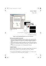
Page 58: ...ster to link your Covermeter to a computer Batch templates Batch readings CoverMaster interface showing reading data measurements CoverMaster interface showing topographical representation of the same...

Page 59: ...90 85 80 75 70 65 60 55 50 45 40 35 30 25 20 15 10 5 0 1 22 36 23 21 31 42 69 34 1 Rows Columns Readings Creation Date Update Date Batch Format High Limit Low Limit Grid Spacing Mean Average Standard...

Page 60: ...tect stainless steel and the SIZE function is therefore removed from the reading screen when this bar grade is selected Borehole Probe The Borehole Probe is used to locate reinforcement bars tendon du...

Page 61: ...ith the scale Note Orthogonal sizing is not possible with the Borehole Probe and the SIZE function is therefore removed from the reading screen when this type of probe is connected to the Covermeter T...

Page 62: ...scaffolding The search head extension arm reduces the need to kneel down and allows the user to scan bridge decks and floor areas from a standing postion The extension arm is only suitable for use wi...

Page 63: ...ars in the sheathing before use The Copper Copper Sulphate half cell probe is intentionally filled with a reserve of saturated Cupric Sulfate solution combined with solid Cupric Sulfate crystals to en...

Page 64: ...w search head If error persists return to Elcometer 3 PROBE Internal error Return to Elcometer 4 PROBE Search head power supply fault Remove probe If error persists the Covermeter is faulty If error c...

Page 65: ...ick Next Follow the remaining on screen instructions to delete the welcome screen 23 STORAGE This Covermeter incorporates a Liquid Crystal Display LCD If the display is heated above 50 C 120 F it may...

Page 66: ...mm 0 65 to 4 8 mm 0 3 bar 9 mm to 75 mm 0 35 to 3 Accuracy up to 65 mm 2 6 depth 2 mm 0 1 over 70 mm 2 8 depth 3 Pitch resolution 16 mm 5 diameter bar at 50 mm 2 depth of cover pitch 75 mm 3 Narrow P...

Page 67: ...r produces a wide range of concrete and coatings inspection equipment Users of the Elcometer 331 Concrete Covermeter may also benefit from the following Elcometer products Elcometer Adhesion and Bond...

Page 68: ...on check block TW33119218 Data transfer cableaq Covermeter to PC T99916217 RS232 to USB transfer cable T99916716 CoverMaster Software TW33119221 Elcometer 331 Model SH to TH upgrade TW33119684 Half ce...

Page 69: ...ole Probe 56 C Calibration 61 Calibration certificates 64 Charger 4 Charging the batteries 4 Cloning a batch 44 Computer Connection cable 64 Computer transferring data to 52 Copying a batch 44 Cover 2...

Page 70: ...5 ALL BATCHES 52 AUTO SWITCH OFF 9 BACKLIGHT 11 BAR 25 BATCH 45 BAUD RATE 17 52 BEEP VOLUME 34 CLEAR STATS 38 CLOCK 16 CLONE BATCH 44 CONTACT 61 COVER 14 CURRENT STATISTICS 52 DATA LOGGER 14 43 DELETE...

Page 71: ...6 Narrow Pitch 56 Specifications 62 Notches in sides of 28 Overview 55 Standard Specifications 62 Storage clip 6 Sensitivity 34 Size Measurement Borehole Probe 56 57 Measuring Automatic 26 Orthogonal...

Page 72: ...68 INDEX R Zoom 49 331 book Page 68 Thursday March 12 2009 9 46 PM...

Reviews: