background image

5

Technical Data Sheet
Monoblock Oil Burner

EK 6.240 / 300 L-E

Technical Data

Burner output

Fuel flow rate

Operating mode

Type of fuel

Burner control box

Flame sensor

Fan motor

Pump unit

          Gear output

          Pressure

Nozzle rod

Nozzle

Oil hoses / External connection

Actuator

Ignition transformer

Weight

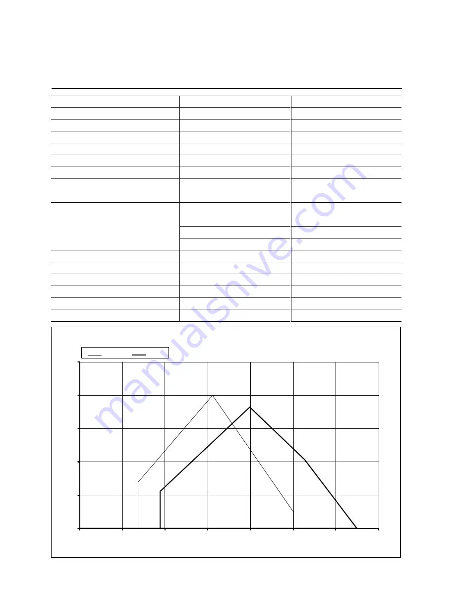
Operating range EK 6.240 / 300 L-E

0

5

10

15

20

25

0

500

1000

1500

2000

2500

3000

3500

6.240 L

6.300 L

Q    Burner output [kW]

F

Air temperature 20°C, test values according to EN 267 (DIN 4787) at 171 m 
above sea level

P

res

su

re

 i

n

 c

om

bu

s

tio

n

 c

ha

m

b

er

 [

m

b

a

r]

6.240 L-E

681 - 2500 kW

57 - 210 kg/h

fully modulating

Light oil EL

BCS / LAL 2 / LOK 16

QRB 3 / RAR 7

400 / 690 V, 50Hz
4,0 kW, 8,5 A, 2800 min-¹

SMG 16026 - 1,1 kW

735 l/h

30 bar

RDN

Thread 7/8"

DN 20 x 1500 / R 1/2"

SAD 15 / STM 40 / MM1004

160 kg

ZA20 140 / ZM20-14

6.300 L-E

940 - 3250 kW

79 - 280 kg/h

fully modulating

Light oil EL

BCS / LAL 2 / LOK 16

QRB 3 / RAR 7

400 / 690 V, 50Hz
4,0 kW, 8,5 A, 2800 min-¹

SMG 16026 - 1,1 kW

735 l/h

30 bar

RDN

Thread 7/8"

DN 20 x 1500 / R 1/2"

SAD 15 / STM 40 / MM1004

160 kg

ZA20 140 / ZM20-14

No.:

102.880.4353

03/05

Technical Data

EK 6.240 / 300 L-E

Summary of Contents for 6.170 L-E

Page 1: ...Operation Manual for the authorized specialist Oil Burner EK 6 7 8 9 L E 03 2005 102 880 2006...

Page 2: ...6 22 Start up Nozzle Selection Type W2 50 23 Start up Return Nozzle Rod RDG 1250 Burner EK 7 EK 9 24 Nozzle selection Sonic 25 Checking Procedure 26 Adjusting Instructions Elektronic Burner Control w...

Page 3: ...in rooms containing aggressive vapours e g spray perchloroethylene hydro carbon tetrachloride solvent etc or tending to heavy dust formation or high air humidity Adequate ventilation must be provided...

Page 4: ...est values according to EN 267 DIN 4787 at 171 m above sea level Pressure in combustion chamber mbar 6 170 L E 501 1800 kW 42 152 kg h fully modulating Light oil EL BCS LAL 2 LOK 16 QRB 3 RAR 7 400 69...

Page 5: ...st values according to EN 267 DIN 4787 at 171 m above sea level Pressure in combustion chamber mbar 6 240 L E 681 2500 kW 57 210 kg h fully modulating Light oil EL BCS LAL 2 LOK 16 QRB 3 RAR 7 400 690...

Page 6: ...at 171 m above sea level Pressure in combustion chamber mbar 7 350 L E 1115 4500 kW 94 380 kg h fully modulating Light oil EL BCS LAL 2 2 LOK 16 QRB 3 RAR 7 400 690 V 50 Hz 5 5 kW 11 7 A 2800 min KL T...

Page 7: ...267 DIN 4787 at 171 m above sea level Pressure in combustion chamber mbar 8 550 L E 2000 6049 kW 168 510 kg h fully modulating Light oil EL BCS LAL 2 2 LOK 16 QRB 3 RAR 7 400 690 V 50 Hz 11 kW 22 5 A...

Page 8: ...4787 at 171 m above sea level Pressure in combustion chamber mbar 9 850 L E 2574 9596 kW 217 809 kg h fully modulating Light oil EL BCS LAL 2 2 LOK 16 QRB 3 RAR 7 400 690 V 50 Hz 18 5 kW 35 A 2800 mi...

Page 9: ...9 Overview Dimensioned Drawings EK 6 L E EK 6 170 200 L E Dimensions in boiler connection plate EK 6 240 300 L E Dimensions in boiler connection plate...

Page 10: ...10 Overview Dimensioned Drawings EK 7 8 L E EK 7 350 450 L E Dimensions in boiler connection plate Type EK 8 550 700 L E Dimensions in boiler connection plate Type...

Page 11: ...11 Overview Dimensioned Drawings EK 9 L E EK 9 850 1000 L E Dimensions in boiler connection plate Type...

Page 12: ...ition of the oil control valve and air damper and thus adjust the oil flow rate in relation to the air flow rate The stepless control will allow the bur ner to be operated at any desired stage between...

Page 13: ...e load will be controlled at any point within the control range depending on the heat demand The two stage sli ding and the stepless control concepts are different only in the control systems used wit...

Page 14: ...grated in pump 311 Return oil pressure switch 312 Feed oil pressure switch 349 Actuator In case of TRD 604 72 hr control items pos 311 312 need to be tested according to special construc tion design o...

Page 15: ...against torsion and a control shaft As the con trol shaft is turned the contoured confi guration of the bush and shaft will change the open cross section for the oil flowing back and thus vary the oil...

Page 16: ...16 Start up Burner Head Settings EK 6 L R E EK 6 170 L R E EK 6 200 L R E EK 6 240 L R E EK 6 300 L R E...

Page 17: ...17 Start up Burner Head Settings EK 7 8 L R E EK 7 350 L R E EK 7 450 L R E EK 8 550 L R E EK 8 550 L R E EK 8 700 L R E...

Page 18: ...18 Start up Burner Head Settings EK 9 L R E EK 9 850 L R E EK 9 1000 L R E...

Page 19: ...the installation materials termi nals and earth connections must be carried out in accordance with the appli cable regulations For the electrical installation of the burner care must be taken to obser...

Page 20: ...ructions The space between the flame tube of the burner D and the boiler lining D1 must be packed with heat resistant material e g Cerafelt This space is not allowed to be lined with brickwork Burner...

Page 21: ...gau ges are mounted to remain on the bur ner they should be fitted with stop valves Oil pressure control feed The feed pressure is controlled by means of the pressure regulator instal led in the pump...

Page 22: ...DWH WR YDU EHFDXVH WKH QHHGOH SRVLWLRQ KDV DQ LPSDFW RQ WKH RLO UHWXUQ IORZ 5HWXUQ QR OH URG W SH 5 1 6WURNH DGMXVWHU FRQWURO QHHGOH GUDXOLF SLVWRQ V VWHP 2LO UHWXUQ FRQQHFWLRQ 2LO VXSSO FRQQHFWLRQ 5H...

Page 23: ...shows the maximum throughput rates of the return nozzles in dependence of the supply oil pressure Supply oil pressure min 20 bar max 30 bar Nominal supply oil pressure 28 bar Return oil pressure min 8...

Page 24: ...ure would keep the slider open Under normal circum stances both locking mechanisms would open at the same time The oil in the forward flow section would exit through the nozzle head to be mixed with t...

Page 25: ...1000 60 with controlled return Light fuel Oil Feed pressure 28bar Return nozzles of the type Sonic Spray are available in different ratings with an angle of spray of 45 60 or 80 The 45 nozzles are pr...

Page 26: ...ional test of the burner program flow Oil system Open all shut off valves of the oil sup ply system The oil solenoid valve in the feed line disconnect on the terminal strip see Circuit Diagram Start b...

Page 27: ...fer to the documentation supplied with the electronic compound control system for the pre operational work on the burner the checking requirements e g actuators limit switches potentio meters etc and...

Page 28: ...grammed by means of the operating and control module or a laptop compu ter If the compound controller is adjusted by means of the operating and display module it will only be possible to correct the c...

Page 29: ...ND 5 AA MA 6 AB MB NOTE Check the zero position of the servomotors prior to start up Technical documentation BCS 300 Dungs Technical data Maximum torque 15 Nm Gear reduction 745 1 Positioning times at...

Page 30: ...nnec tion with the electronic burner control systems of the firm Lamtec Technical data Voltage 230V AC Frequency 50 Hz Angle of rotation 90 Running time 40 sec for 90 Torque 15 Nm Static holding momen...

Page 31: ...ker attached to the housing side wall Functional test without burner start After the electronic compound controller has been connected electrically pro ceed with adjusting the potentiometers of the ac...

Page 32: ...cc to DIN EN in pumps without quick action stop valve DSF 146 F 0 10 bar 0 5 2 5 bar Return line acc to TRD 604 72h DSB 158 F 3 25 bar 1 0 4 3 bar Feed line acc to TRD 604 72h Air pressure switch The...

Page 33: ...al between voltage on terminal 19 and terminal 20 interval between valve 2 and controller enable t6 After flushing time t7 Interval between start command and voltage on terminal 7 t11 Air damper opera...

Page 34: ...3 flame sensor is mounted to burners with intermittent mode of operation which are shut down within 24 hours Application Burners operated in continuous or inter mittent mode for periods in excess of...

Page 35: ...ped thread Item 3 to act as a forcing screw Tighten this bolt to force off of the bush Remove the loosened disk unit by hand without hammer blows and taking care not to damage it Mounting the fan impe...

Page 36: ...tests Fuel throughput rate adjustment Heating chamber temperature intake temperature Exhaust gas temperature Pressure in combustion chamber and exhaust gas pipe CO2 and O2 contents of exhaust gases C...

Page 37: ...12 97 0 40 15 11 3 40 12 89 0 50 15 03 3 50 12 82 0 60 14 96 3 60 12 75 0 70 14 88 3 70 12 67 0 80 14 81 3 80 12 60 0 90 14 74 3 90 12 53 1 00 14 66 4 00 12 45 1 10 14 59 4 10 12 38 1 20 14 52 4 20 12...

Page 38: ...electrodes Cracked insulator Replace insulator Defective igni tion transformer Replace transformer Defective auto matic furnace controller Replace controller Burnt ignition cable Replace cable search...

Page 39: ...ause Remedy Dirty flame sen sor Clean flame sensor Burner fails to start Check connection of automatic fur nace controller Trouble lamp lights flame trouble Unlock and search for cause Weak flame sen...

Page 40: ...to stop The symbol shown above the reading of the indicator will identify the type of trouble No start e g because the CLOSED signal from the limit change over switch Z or auxiliary switch M is not a...

Page 41: ...illing line 10 Limit transmitter 11 Vent line 12 Pump unit 13 Pressure holding valvel Stepless control with supply pump and ring line system Stepless control direct intake 1 Burner blower 2 Oil filter...

Page 42: ...42...

Page 43: ...43 Customer Service ELCO GmbH D 64546 M rfelden Walldorf ELCO Austria GmbH A 2544 Leobersdorf ELCOTHERM AG CH 7324 Vilters ELCO Rendamax B V NL 1410 AB Naarden ELCO Belgium n v s a B 1731 Zellik...

Reviews: