


w w w . e l a t i o n l i g h t i n g . c o m
2
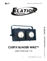
CUEPIX BLINDER WW2
™
User Manual 1.0
©2013 by ELATION PROFESSIONAL
. All Rights Reserved. Information, specifications, diagrams, images, and
instructions herein are subject to change without notice. ELATION PROFESSIONAL logo and identifying product
names and numbers herein are trademarks of ELATION PROFESSIONAL. Copyright protection claimed
includes all forms and matters of copyrightable materials and information now allowed by statutory or judicial
law or hereinafter granted. Product names used in this document may be trademarks or registered
trademarks of their respective companies and are hereby acknowledged. All non-ELATION brands and
product names are trademarks or registered trademarks of their respective companies.
ELATION PROFESSIONAL
and all affiliated companies hereby disclaim any and all liabilities for property,
equipment, building, and electrical damages, injuries to any persons, and direct or indirect economic loss
associated with the use or reliance of any information contained within this document, and/or as a result of
the improper, unsafe, insufficient and negligent assembly, installation, rigging, and operation of this product.
Elation Professional Corporate Headquarters
|
6122 S. Eastern Ave.
|
Los Angeles, CA. 90040
323-582-3322
|
323-832-9142 fax
|
www.elationlighting.com
|
Elation Professional Florida
|
13185 NW 47
th
Ave. | Miami Gardens, FL. 33054
Elation Professional B.V. |
Junostraat 2
|
6468 EW Kerkrade, Netherlands
+31 45 546 85 66
|
+31 45 546 85 96 fax
|
www.elationlighting.eu
|