Page 13 of 46
User Manual
ECD-3-nano
Release 1.52
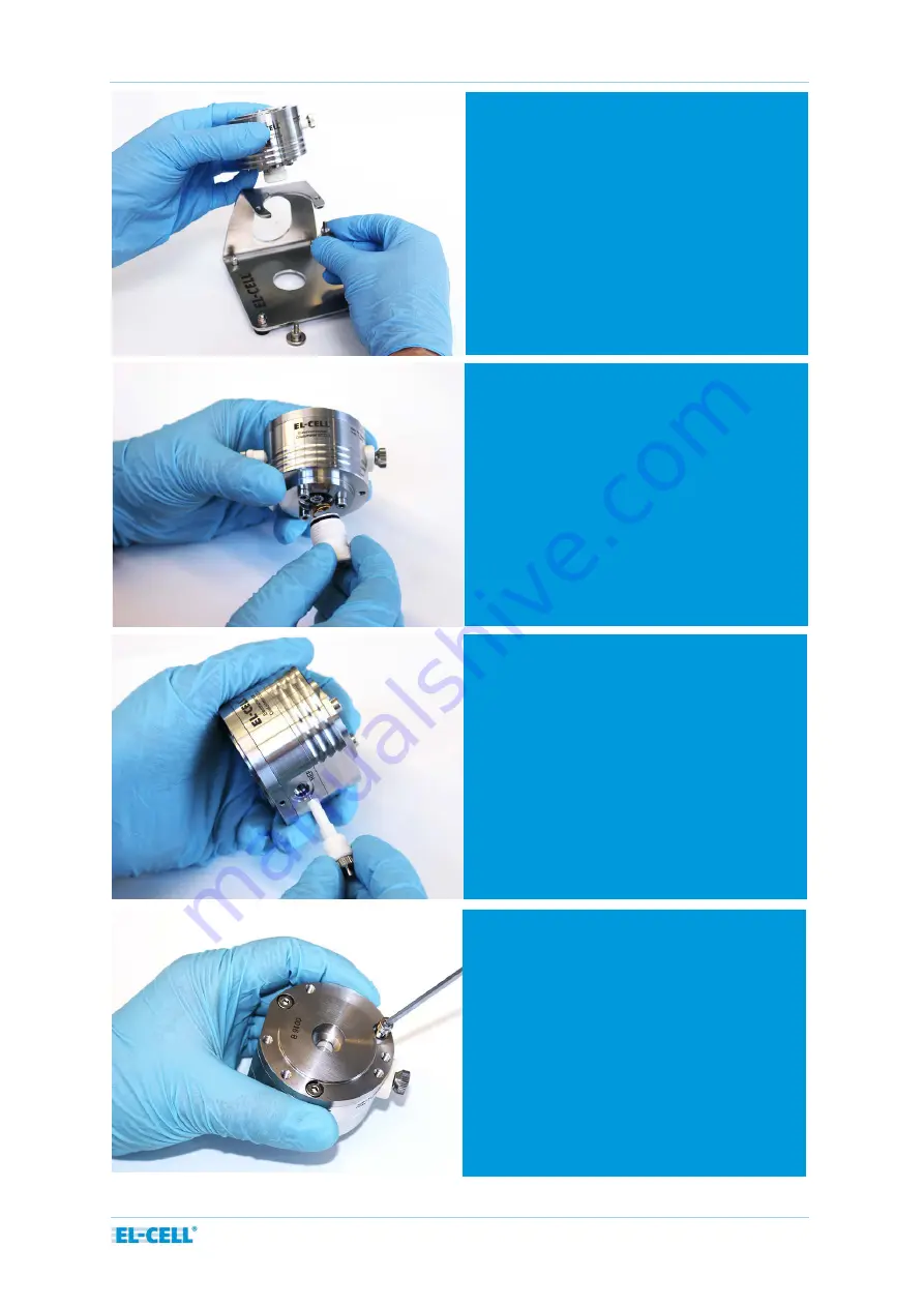
6.4
Screw off the cell body from the
bracket.
6.5
Unscrew the spring load from the cell
body.
6.6
Unscrew the reference electrode.
6.7
Remove the cover flange
Page 1: ... 2017 EL Cell GmbH 2021 EL Cell GmbH User Manual Release 1 52 Electrochemical dilatometer ECD 3 nano ...
Page 2: ...ies EL Cell GmbH maintains the right to make changes without further notice to products described in this manual to improve reliability function or design EL Cell GmbH does not assume any liability arising from the use or application of this product EL Cell GmbH Tempowerkring 8 21079 Hamburg Germany phone 49 40 79012 737 fax 49 40 79012 736 e mail info el cell com web www el cell com ...
Page 3: ...e the glove box 26 9 EC Link Software Installation 31 10 Calibration and Settings 31 11 Recording the Displacement Signal with an External Potentiostat 32 12 Using the Reference Electrode 33 13 Using the valve 34 14 Choosing the appropriate spacer disc 35 15 Dilatometer Disassembly and Cleaning 36 16 Care Instructions 37 17 Consumables 37 18 Spare Parts 38 Components Sensor Unit 38 Components Cell...
Page 4: ...Page 4 of 46 User Manual ECD 3 nano Release 1 52 Spring load ECD 3 assy 42 REF electrode ECD long assy 1 4404 43 19 Connector and Cable Pin out 44 20 Technical support 46 21 Warranty 46 ...
Page 5: ...in position The upper working electrode WE is sealed by means of a thin metal foil through which any charge induced thickness change is transmitted towards the sensor load unit above This working principle allows determining the height change of the working electrode without any interference from that of the counter electrode CE A high resolution capacitive displacement transducer detects dimensio...
Page 6: ...Page 6 of 46 User Manual ECD 3 nano Release 1 52 Basic structure of the ECD 3 nano Sensor unit Details shown on the following page Cell body Bracket ...
Page 7: ...D 3 nano Release 1 52 Cut drawing of the ECD 3 nano Sensor cable Micrometer screw Sensor plunger Excenter Locking screw Spacer disc Glass T Frit Shut off valve Capacitive sensor Flexure Load Sensor Tip Reference electrode Piston ...
Page 8: ...ignals 10 to 10 V for displacement and temperature Integrated USB data logger for the recording of displacement temperature cell potentials and current 3 electrode electrochemical cell 3 Technical Data Working upper electrode bound electrode film or single crystal grain max sample size 10 mm x 1 mm diameter x thickness Counter lower electrode 12 mm diameter Load on working electrode 1 N Electrolyt...
Page 9: ...ven below to verify that you have received all of the required components Contact EL CELL if anything is missing or damaged NOTE Damaged shipments must remain within the original packaging for freight company inspection List of Components 1 ECD 3 nano dilatometer ECD3 00 0001 A assembled 2 Box ECD 3 nano ECE1 00 0006 F assembled 3 Sensor GND cable ECE1 00 0041 A 4 Sensor cable PISeca SEN9023 5 ECD...
Page 10: ... C 14 1 x PTFE Seal ECD 33 3 x 1 8 mm 3 pcs ECC1 01 0043 D 3 15 3 x O Ring 33 mm x 1 78 mm DIC9034 16 3 x O Ring 50 5 mm x 1 78 mm DIC9038 17 T Frit 10 12 5 ECC1 00 0041 B 18 Stiff Plate ECD1 00 0041 A 19 3 x Ferrule 1 5 mm short top part ECC1 00 0029 H 20 Membrane aprotic 1 4404 ECC1 00 0019 D 21 Spacer disc Set 2 1 2 3 mm 3 pcs ECC1 01 0012 F 22 Separator GF A 12 mm x 0 26 mm 10 pcs ECC1 01 0012...
Page 11: ... ECD1 00 0900 A 24 Allen wrench set 0 9 1 3 1 5 2 4 pcs ECC1 01 0028 A 25 Open end wrench AF7 ECC1 09 2037 A 26 Removing tool for ECD 3 piston ECC1 09 2005 A 27 Allen screw driver 2 5 mm WZG9003 28 Spherical allen screw driver 3 mm WZG9002 29 Tweezer antiacid stainless WZG9001 8 ...
Page 12: ... General advise Practice the assembly procedure outside the glove box with dummy components before going for the real experiment Make sure you have understood the how and why of each single step Ask us otherwise 6 1 After unpacking the ECD 3 remove the transport lock from the sensor unit 6 3 Unscrew and detach the sensor unit 6 2 Unscrew the two inner screws first only then the two outer screws ...
Page 13: ...ge 13 of 46 User Manual ECD 3 nano Release 1 52 6 4 Screw off the cell body from the bracket 6 5 Unscrew the spring load from the cell body 6 6 Unscrew the reference electrode 6 7 Remove the cover flange ...
Page 14: ... plate below the cover flange This plate is for transport only For the actual experiment replace the plate by the provided metal membrane 6 10 Now the frit flange with the PTFE Seal and the piston in the middle are visible 6 9 Remove the stiff plate or membrane from the cell body 6 11 Pull the frit flange out of the cell body ...
Page 15: ... springs inside piston and allows it to be pulled out 6 13 Pull the piston out of the frit flange by using the dedicated removal tool We advise you to hold the removal tool between your thumb and index finger as shown in the picture This allows the piston to be pulled out safely Remove the T Frit afterwards 6 14 Remove the three screws that fix the dead volume cover ...
Page 16: ...Page 16 of 46 User Manual ECD 3 nano Release 1 52 6 15 Remove the dead volume cover and both O Rings 6 16 Unscrew the valve stem and the valve body ...
Page 17: ...kness depends on working electrode thickness 3 T frit 4 Cover flange with three screws 5 Dead volume cover with three screws 6 ECD 3 base body 7 Frit flange 8 Spring load 9 Reference electrode 10 Piston PTFE sealing internal thread ECD 3 11 O Ring 50 5 x 1 78 mm EPDM 12 2 x O Ring 33 05 x 1 78 mm EPDM 13 Socket screw 14 PE Seal for ECD 3 33 mm x 1 6 mm 15 Ferrule 1 5 mm PTFE 16 Shut off valve Note...
Page 18: ...the chemicals with care 7 1 Inside the glove box Insert the T frit with the smaller side pointing downwards into the frit flange Note Make sure that the inside of the frit flange does not get damaged scratched when inserting the T frit Replace the frit flange as necessary 7 2 Inside the glove box Put a glass fiber separator 12 mm diameter on top of the frit 7 3 Inside the glove box Insert the lith...
Page 19: ...g 17 PTFE Seal ECD 3 piston on the piston The outward curved side of the sealing rings must face away from the piston see sketch below 7 5 Inside the glove box Add the thrust screw Align it so that the mark on the thrust screw is centered on the recess in the piston 7 6 Inside the glove box Tighten the socket screw firmly with the provided allen wrench ...
Page 20: ...d together 7 8 Inside the glove box Tighten the socket screw at the end of the pistol using the tools provided Important note Only use a frit flange with an attached metal support ring as shown in the picture Otherwise the frit flange may be damaged when trying to tighten the screw 7 9 Inside the glove box Insert the two big O rings and attach the dead volume cover to the base body ...
Page 21: ...ooves at the frit flange and the cell base body are properly aligned Note Make sure that the frit flange is fully inserted You may otherwise damage the cell 7 11 Inside the glove box Add 320 420 μl of electrolyte using an pipette 7 12 Inside the glove box Place the working electrode with the active side pointing downwards on top of the T Frit ...
Page 22: ...sure it is inserted correctly 7 14 Inside the glove box Put the spacer disc on top of the electrode make sure that it is placed in the center of the electrode The proper spacer disc thickness depends on the working electrode thickness see chapter 14 7 15 Inside the glove box Then put the membrane on top ...
Page 23: ... Inside the glove box Now close the cell body with the three cover screws In the first step tighten the screws slightly with the enclosed screwdriver 7 18 Inside the glove box After that we recommend using the allen key to tighten the screws in small increments on all three sides until they reach the stop ...
Page 24: ...load into the cell base 7 21 Inside the glove box Pick up some lithium with the reference pin Make sure that the hole of the reference pin is completely filled with lithium metal Incomplete filling may result in scatter noise of the WE potential Make sure that the reference pin and the PTFE ferrule are not corroded or damaged The PTFE ferrule must be white and must not show any black coloration Re...
Page 25: ... 22 Inside the glove box Lithium must not come into contact with the PTFE ferrule see arrow 7 23 Inside the glove box Attach the reference pin firmly to the cell body 7 24 Inside the glove box Push onto the back of the reference pin while screwing it in ...
Page 26: ...x 7 26 Hook the assembly into the bracket and fasten it with the two knurled screws 3 2 1 7 27 Unlock the locking screw 1 and the excenter 2 Then turn the micrometer screw 3 clockwise until the sensor tip is in the upmost position Note Not following the above instruction may result in damage of the membrane the glass frit or even the sensor unit when attaching the sensor unit onto the dilatometer ...
Page 27: ...Page 27 of 46 User Manual ECD 3 nano Release 1 52 7 28 Attach the sensor unit onto the dilatometer cell 7 29 Fasten the screws to fix the sensor unit ...
Page 28: ...he photo below We highly recommend operating the dilatometer in a temperature controlled environment 1 ECD cell cable 2 Sensor GND cable 3 Sensor cable 4 Power cord 90 to 240V AC input 5 DC cable 15V 15V 5V DC output 6 USB 2 0 cable 7 Optional analog output cable 1 3 4 5 6 7 5 4 6 7 3 2 1 ...
Page 29: ...t the controller box of the ECD 3 nano Any yellow LED indicates a valid position 7 33 For best accuracy and resolution adjust the sensor approximately in central position 7 30 Unlock the locking screw 1 and the excenter 2 if not already done 2 1 7 31 Lower the sensor tip by turning the micrometer screw counter clockwise ...
Page 30: ...g the electrochemical cycle we recommend holding the cell at constant potential or open circuit for several hours to allow for baseline stabilization The initial rest period helps to discern charging induced dimensional changes from the initial creeping NOTE All materials display a more or less pronounced creeping They tend to shrink when applying a load and to swell when removing this load A majo...
Page 31: ... on your screen Once installation is finished plug in the provided USB cable into both the host PC and the ECD 3 nano controller box Launch the EC Link data logger software if not already done After a few seconds EC Link should report a valid connection and you are ready to start the measurement Additional information on the EC Link software can be found in a separate manual https el cell com supp...
Page 32: ... described as an example The Biologic potentiostats feature two analog inputs that are used here to record both displacement and temperature 1 Connect the 9 pin Sub D connector of the optional analog output cable to the analog input of the respective VMP3 channel 2 In the Biologic EC Lab software load the experiment settings ECD 3 nano mps provided on the EC Link installation media The settings ar...
Page 33: ...f the cell stack it is advised to push onto the back of the reference pin while screwing in the pin NOTES Avoid any direct contact of the PTFE ferrule with lithium metal PTFE is being reduced to black and porous carbon when getting in contact with lithium The standard dilatometer comes with a stainless steel reference pin which is good for use with lithium metal In contrast the gold reference pin ...
Page 34: ...e gently by hand Excessive torque may damage the valve Some valve parts may get into electrolyte contact It is therefore advised to unscrew the valve seating and the valve stem after use The two O ring seals and the PTFE ferrule may stay in place Wash with plenty of water or other appropriate solvent Dry the valve parts in the disassembled state 80 C vacuum overnight before reassembly inside the g...
Page 35: ...prised of the spacer disc current collector and the working electrode Choose a proper spacer disc height depending on the thickness of your electrode Spacer discs are available in different heights ranging from 0 9 mm to 2 3 mm in 0 1 mm steps If in doubt choose the next higher spacer disc We recommend using the 2 3 mm spacer disc for all electrodes in the thickness range 0 to 150 µm Sensor Membra...
Page 36: ...e dilatometer cell and the sensor unit 2 Remove the dilatometer cell from the temperature chamber Then follow the instructions as described in chapter 6 starting at step 3 Clean all wetted parts right after disassembly Ultrasonic cleaning with water and or detergent wash is recommended Valves and tubing may clog if not properly purged with water or other solvent After cleaning dry all parts in vac...
Page 37: ...g 33 05 x 1 78 mm 10 pcs DIC9034 X Ferrule 1 5 10 pcs ECC1 00 0029 H X O Ring 50 5 x 1 78 mm 10 pcs DIC9038 X PTFE Seal for ECD 33 x 1 6 3 pcs ECC1 01 0043 D 3 PTFE seal for ECD 3 piston 3 pcs ECC1 01 0044 C 3 O Ring 9 75 mm x 1 78 mm AP370 10 pcs DIC9006 X Spacer disc set 2 1 2 3 ECC1 01 0012 F Spacer disc set 1 8 2 0 ECC1 01 0012 G Spacer disc set 1 5 1 7 ECC1 01 0012 H Spacer disc set 1 2 1 4 E...
Page 38: ...6 User Manual ECD 3 nano Release 1 52 Socket screw DIN 912 M4x12 18 Spare Parts Components Sensor Unit ECD1 00 0030 A There are no further spare parts available for the sensor unit For repair please contact EL CELL ...
Page 39: ...Page 39 of 46 User Manual ECD 3 nano Release 1 52 Components Cell Body ECD3 00 0002 A ...
Page 40: ... Manual ECD 3 nano Release 1 52 Shut off valve ECD 3 assy ECC1 00 0155 B Ferrule 1 0 ECC1 00 0029 B O Ring 5x1 mm AP370 DIC9036 O Ring 2x1 mm AP312 DIC9037 Valve Seating ECD 3 ECC1 00 0153 C Valve Stem ECD ECC1 00 0063 B ...
Page 41: ...Page 41 of 46 User Manual ECD 3 nano Release 1 52 Central CE piston ECD 3 PE sealed screwed ECD3 00 0006 D ...
Page 42: ... Release 1 52 Spring load ECD 3 assy ECD3 00 0008 A Compression Spring 1 2 x 9 8 x 19 2 x 3 5 AU FED9021 Spring Ram ECD 3 ECC1 00 0022 E O Ring 6 75 x 1 78 mm AP380 DIC9039 O Ring 14 x 1 5 mm AP370 DIC9032 Spring Ram ECD 3 ECC1 00 0021 C ...
Page 43: ...CD long assy 1 4404 ECD1 00 0009 D Ferrule 1 5 short top part ECC1 00 0029 H Fitting long II with cone ECC1 00 0039 N Ref pin ECD long 1 4404 ECD1 00 0050 A Compression spring 1 4310 Au FED9017 Reference connection tip ECC1 00 0331 A Hollow screw ECD 3 ECC1 00 0040 A ...
Page 44: ... box the other end is terminated by 2 mm banana connectors A Pt100 sensor is located beneath the black shrink tube at the end of the cable pointing to the dilatometer The cable shield is tied to the Sub D connector housing Pin Signal Cable Color Color of 2 mm connector 1 V1 Red Red 2 V2 Blue Blue 3 4 REF Grey Grey 5 I2 Yellow Yellow 6 7 8 9 10 I2 Green Green 11 Pt100 1 Brown 12 Pt100 2 White 13 14...
Page 45: ...m2 TP shielded ECE1 00 0039 B Both connector housings are tied to the cable shield The cable shield is connected to GND IEEE 1394 to Box Sub D M9 to Biologic AUX Input Pin Signal Cable Color Pin Signal 1 2 GND Black 7 GND 3 4 Temperature Blue 6 Analog IN2 5 6 Displacement Green 1 Analog IN1 ...
Page 46: ...ted Warranty does not cover defects damage or nonconformity resulting from abuse misuse neglect lack of reasonable care modification or the attachment of improper devices to the goods This Limited Warranty does not cover expendable items This warranty is void when repairs are performed by a non authorized person or service center At Seller s option repairs or replacements will be made on site or a...