INSTALLATION MANUAL
LIQUID COOLING KIT
EK-Quantum
Power Kit RX 6800/6900 D-RGB P360 - AMD Edition
1st Revision, November 26, 2020
Page 1: ...INSTALLATION MANUAL LIQUID COOLING KIT EK Quantum Power Kit RX 6800 6900 D RGB P360 AMD Edition 1st Revision November 26 2020...
Page 2: ...results EK recommends the use of EK CryoFuel coolants 8 The use of corrosion inhibiting coolants is always recommended for any liquid cooling system EKWB recommends any of the EK Cryofuel for worry f...
Page 3: ...CATIONS AND WATER BLOCK PARTS 30 PREPARING THE GRAPHICS CARD 31 REMOVING THE STOCK BACKPLATE 31 REMOVING THE STOCK COOLER 31 CHANGING THE STOCK 2 SLOT I O BRACKET FOR THE SINGLE SLOT I O BRACKET 32 CL...
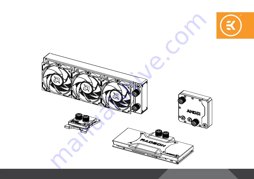
Page 4: ...Cable Y Splitter 1 Radiator 1 ZMT Tube Single Slot I O Bracket 1 GPU Water Block 1 With a Backplate and Mounting Mechanism CPU Water Block 1 With a Mounting Mechanism Reservoir 1 With a Mounting Mecha...
Page 5: ...ing Bottle EK Loop Angled Bracket 120mm 1 With a Mounting Mechanism EK Loop Soft Tube Cutter 1 Foldable Filling Bottle 1 ATX Bridging Plug 1 EK Loop CMS 1 EK D RGB 6 Way Splitter Cable 1 EK CryoFuel B...
Page 6: ...6 RADIATOR SPACE REQUIREMENTS 130mm 5 75 in 400 mm 15 75 in 40 mm 1 58in 130mm 5 75 in 400 mm 15 75 in 40 mm 1 58in...
Page 7: ...parts of the system 4 It is best practice to do a proper 24 hour leak test before using your computer 5 If you spot any leaks turn off the power immediately 6 Optimize tube length to prevent excessiv...
Page 8: ...8 INSTALLING THE CPU WATER BLOCK...
Page 9: ...9 BOX CONTENTS Thumb Nut 4 Thermal Grease 1 Allen Key 2 5mm 1 Standoff 4 EK Quantum Velocity D RGB AMD Ryzen Edition CPU Water Block 1 Rubber Gasket 1 Metal Backplate 1 M4 x 0 8 PA Washer 4 Spring 4...
Page 10: ...ITY This CPU liquid cooling unit is pre assembled for use with modern AMD desktop socket type motherboards By default out of the box this water block supports the following CPU sockets AMD socket AMx...
Page 11: ...11 WATER BLOCK DIMENSIONS 87 102 54 90 24...
Page 12: ...ons Dimensions LxHxW 102 x 87 x 24 mm D RGB Adressable RGB Cable Length 300 mm D RGB LED Count 20 D RGB Connector Standard 3 Pin 5V Data Blocked Ground EK BADGE JET PLATE SEALING GASKET LED COVER D RG...
Page 13: ...o identify those parts AMD FACTORY BACKPLATE UNC 6 32 SCREWS HOLD DOWN CLAMPS STEP 1 INSTALLING THE WATER BLOCK STEP 2 Turn your motherboard face down and position the Rubber Gasket and Backplate dire...
Page 14: ...ded STANDOFF PA WASHER STEP 3 STEP 4 Wipe the IHS clean using a non abrasive cloth or Q tip as shown in the image Once it s clean apply a line of Thermal Compound to one edge of the IHS and use a plas...
Page 15: ...ch standoff before tightening them two revolutions at once in a cross pattern Do not tighten them fully until all of them are partially screwed in STEP 5 THUMB NUT COILED SPRING STEP 6 Tighten the fit...
Page 16: ...ays strive to achieve the unidirectional airflow throughout the chassis METHOD 1 STEP 1 Take four 4 UNC 6 32 x 30mm screws for each fan and screw them in UsetheenclosedAllenkeytotightenthescrewsinthec...
Page 17: ...them into the threaded holes of the radiator Tighten them in a clockwise direction using the enclosed Allen key STEP 3 Radiator UNC 6 32 x 5 Screw Fan STEP 4 Install the compression fitting on both G1...
Page 18: ...ve standard pre drilled fan mounting holes and you should look for those with a spacing of 105mm for standard 120mm computer cooling fans STEP 1 STEP 2 Align the holes of the radiator and fans with th...
Page 19: ...on until the gasket underneath is compressed The installation of the radiator and its cooling fans is now complete OPTIONAL EK Quantum Power Kit also comes with four pieces of EK Torque 90 Angled Fitt...
Page 20: ...as it utilizes a standard fan mounting hole pattern with 105 mm spacing the same as all EK radiators The mounting holes have standard M4 threads with maximum engagement of 10mm Use of longer screws or...
Page 21: ...21 FLT Reservoir can be mount in multiple directions Vertically and horizontally position is optional Do not mount FLT Reservoir when the pump is in dead position...
Page 22: ...ing the included M4 screws you can mount the reservoir directly to your chassis or any other standard fan mounting location INSTALLING THE PUMP RESERVOIR UNIT DIRECTLY TO THE CHASSIS M4 x 10 DIN 7984...
Page 23: ...p is required EK supplies a pair of FLT mounts along with M4 nuts washers and additional screws They can be positioned across any pair of mounting holes in several orientations STEP 1 Position the mou...
Page 24: ...nt the flat reservoir to a fan INSTALLATION OPTIONS 120 mm Fan UNC 6 32 x 30 ISO 7380 Screw 3b Using 30mm long screws supplied with your radiator the reservoir can be mounted onto the radiator and 25m...
Page 25: ...x 10 DIN 7984 SCREW M4 NUT 3d Lastly the supplied M4 nuts washers and M4x10 screws may be used to secure the reservoir to a case with the mounts This is useful when there is no clearance behind for th...
Page 26: ...tailed instructions click on the link below https www ekwb com shop EK IM EK IM 3831109825365 pdf EK Quantum Kinetic FLT has two inlet and two outlet ports one of each must be used All 4 unused ports...
Page 27: ...27 INSTALLING THE GPU WATER BLOCK...
Page 28: ...al Pad F 1 5 mm 3 pcs Thermal Pad F 2 0 mm 1 pcs Thermal Grease 1 pc M2 5x8 AX1 Screw 7 pcs M2 5x4 AX1 Screw 30 pcs EK Quantum Vector RX 6800 6900 D RGB AMD Radeon Edition PVC Washer M2 5 28 pcs 120 m...
Page 29: ...29 WATER BLOCK DIMENSIONS 120 05 mm 132 55 mm 266 20 mm 119 10 mm 147 10 mm 16 50 mm 21 35 mm...
Page 30: ...e RGB Cable Length 500 mm D RGB LED Count 14 D RGB Connector Standard 3 Pin 5V Data Blocked Ground M3 x 6 DIN7991 SCREW ALU LED COVER M4 x 25 DIN7984 SCREW M6 60 STANDOFF M2 5 STANDOFF M3 x 11 DIN7991...
Page 31: ...Backplate and the Retention bracket from the backside of the GPU STEP 2 REMOVING THE STOCK COOLER Use the Phillips head screwdriver to unscrew the sixteen 16 marked screws thirteen 13 from the bottom...
Page 32: ...GLE SLOT BRACKET M2 5 x 4 AX1 SCREW SINGLE SLOT BRACKET STOCK SCREWS 4x For this Step you will need To remove the I O Bracket unscrew all five 5 screws marked in a diagram Save the four 4 marked screw...
Page 33: ...tovers After that remove all remaining stock thermal pads from the PCB STEP 1 Your GPU water block comes with thermal pads that have to be cut into smaller pieces to cover all the VRM components such...
Page 34: ...p Thermal Pad F 1 0mm Thermal Grease STEP 1 Apply the enclosed EK TIM Ectotherm thermal grease thermal compound on the CPU heat spreader IHS as shown in the image The layer of the thermal compound mus...
Page 35: ...gned mounting holes of the PCB with holes of the water block same applies to other tops Pay attention not to use too much force when pressing the block down to the PCB since chip dies are prone to cra...
Page 36: ...36 The screws must be present on the places marked below BACKPLATE DIMENSIONS INSTALLING THE BACKPLATE 110 05 mm 107 55 mm 266 20 mm 6 20 mm...
Page 37: ...vide you with more than an adequate quantity of thermal pads to complete this Step CAUTION You must remove the protective foil from both sides of the thermal pad before installation Replacement therma...
Page 38: ...ING THE BACKPLATE Place the backplate on the PCB and make sure all holes are aligned Position an M2 5X8 AX1 screw in each of the six 6 mounting holes as shown in the image and tighten them evenly with...
Page 39: ...e graphics card Avoid all unnecessary manipulation of the water block assembly that might damage your card or water block If necessary temporarily remove the water block to check for uniform surface c...
Page 40: ...using EK fittings with all EK water blocks CAUTION When using connectors other than EK fittings pay special attention to the length of the fittings male G1 4 thread 5mm is the maximum G1 4 thread len...
Page 41: ...length to spare You can always shorten the tube afterward For the coolant to flow without restriction make sure the tube is not bent or twisted STEP 2 STEP 3 If you assembled the components according...
Page 42: ...can do that by forcing it to slide over the edge as far as it goes If needed heat the tube in warm water STEP 4 Fitting Barb Fitting Ring Tubing STEP 5 Slide the fitting ring toward the fitting barb a...
Page 43: ...o the 4 pin female Molex connector of the power supply STEP 1 STEP 2 Take the 4 pin PWM female connector and plug it to the male PWM header located on the motherboard If possible always use the CPU de...
Page 44: ...e fans with male connectors on the fan splitter cable The EK Cable Y splitter comes enclosed with the Kit STEP 1 Fan Splitter Cable Fan Connector STEP 2 Connect the female splitter connector to a head...
Page 45: ...r 2 Plug the EK ATX Bridging Plug enclosed into the 24 pin ATX PSU cable which allows jump starting your computer This procedure requires only the pump to be connected to the power supply PSU Everythi...
Page 46: ...n layout on the header is as follows 5V Data Empty Ground Please ensure that the arrow indicated on the connector is plugged into the 5V line as indicated on your motherboard If you connect LEDs to th...
Page 47: ...plug of your reservoir by unscrewing it in a counter clockwise direction It is recommended to protect the exposed hardware with a few paper towels in case there is a leak or you accidentally spill th...
Page 48: ...m below the fill port Screw the reservoir top cover back in a clockwise direction STEP 5 Tilt your PC chassis in different directions to remove any air that might have remained trapped inside the radi...
Page 49: ...TS Once a year you should check if the pump and fans are running as they should The pump and fans must run silently without any rattling noises and must react to PWM duty cycle changes All imperfectio...
Page 50: ...r assistance please contact http support ekwb com EKWB d o o Pod lipami 18 1218 Komenda Slovenia EU EKWaterBlocks EKWaterBlocks ekwaterblocks ekwaterblocks EKWBofficial SUPPORT AND SERVICE SOCIAL MEDI...